
link270
.
- Joined
- Jul 4, 2017
- Messages
- 125
- Likes
- 108
Hey guys,
I've been putting off starting a worklog for a bit now, as I'm pretty new to this so I wanted to make sure I understood the basics and got relatively far before posting one. I have finally gotten to a point where I feel I can share my work and work towards finishing.
So far here's what I've done:
What I still need to do:
Heres a bunch of pictures of my current position:
-Close up of my custom reg board
-Batteries/charging/LED on/off indicator
-Trimmed board closeup
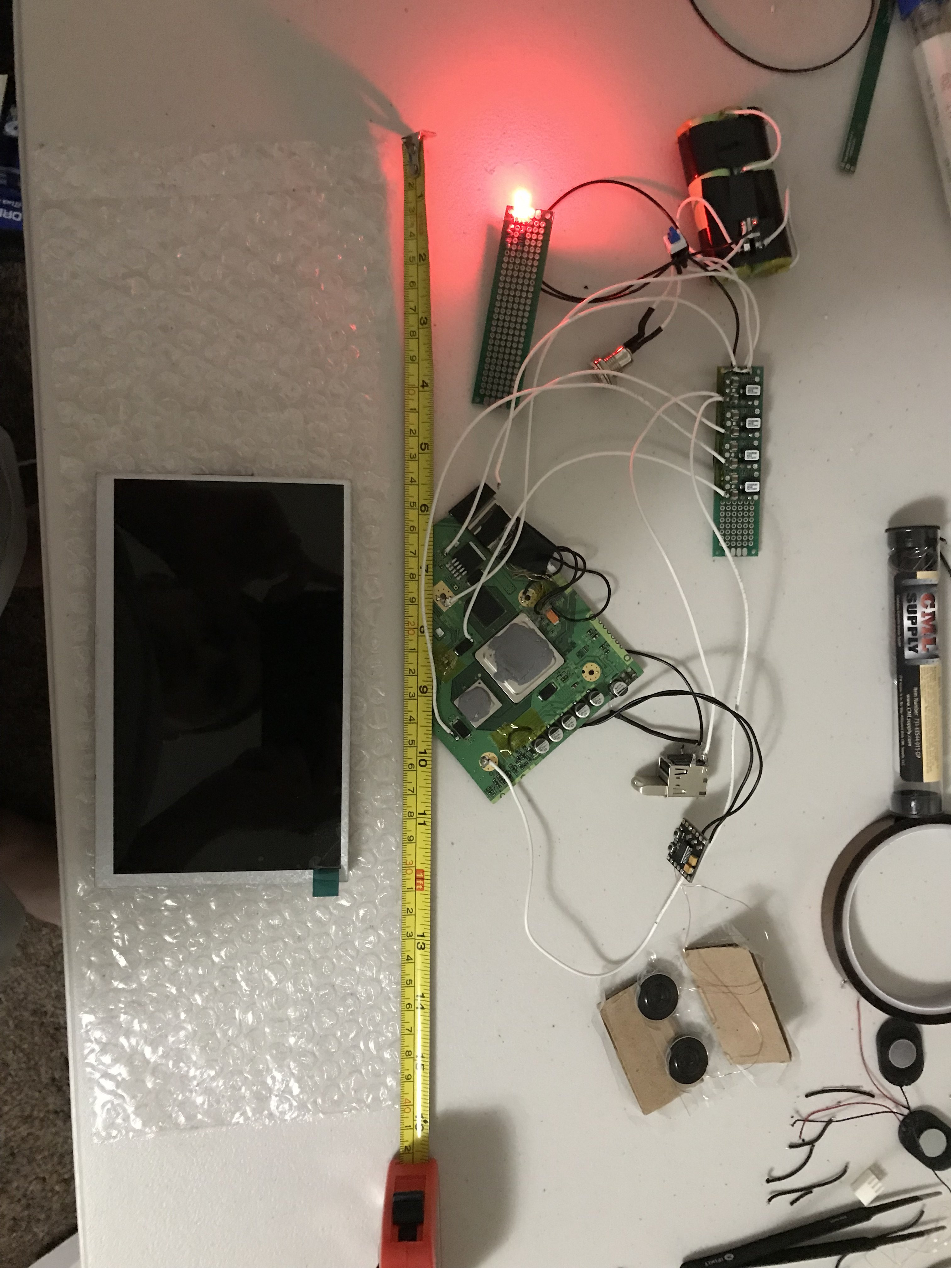
-General idea of scale of each component
-A really really general idea of the screen/button layout. At the moment I am planning to use the GC buttons and maybe Dpad with 3DS sliders. I've got the buttons all hooked up to some perfboard with the ends I need to connect to soldered onto their own pads, that way I can wire it up easily and hopefully keep it a little cleaner.
Anyways, there's my work thus far. Feel free to give me any feedback or suggestions!
Thanks again to everyone being so helpful around here, I've wanted to do a portable ever since I saw a portable n64 guide back around 2010 but I'd never be able to get this far without this community! I'm excited to finish this one up and continue with updates then get started on some other projects as well.
I've been putting off starting a worklog for a bit now, as I'm pretty new to this so I wanted to make sure I understood the basics and got relatively far before posting one. I have finally gotten to a point where I feel I can share my work and work towards finishing.
So far here's what I've done:
- Bought a better soldering iron and a multimeter
- Installed noWIFI/portabilizemii
- Harvested the buttons from an old GC controller
- Rewired the GC controller right onto the Wii motherboard, as mine didn't have the GC ports soldered on
- Practiced and practiced and practiced soldering until I successfully relocated bluetooth and USB and confirmed them working
- Relocated U10, went surprisingly smoothly and worked first try
- Order a bunch of parts (Resistors, capacitors, speakers, an Audio Amp, GC+ (Still waiting on this), Powermii lite (I'm planning to use this on my second attempt) and a ton more stuff
- Wired up a 2S1P battery pack and made sure the charger worked properly. (I will probably add 2 more cells for a 2S2P)
- Got everything for my custom regulators, wired them up onto some perf board in an attempt to keep it neat looking, the voltages all came out good
- Bought another wii off eBay (I guess I have to make a second portable now.
 )
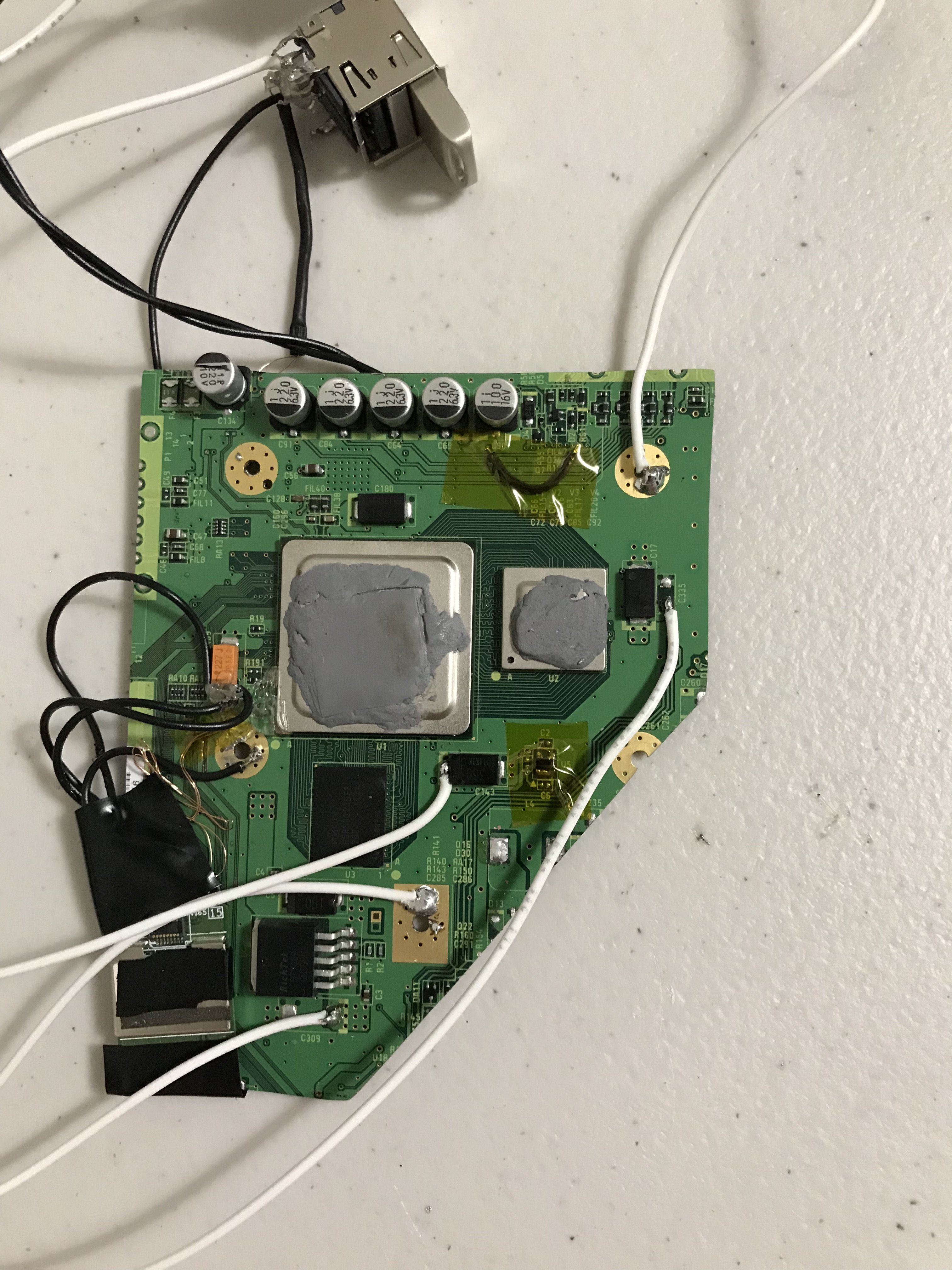
) - Taped up and trimmed the board, it went a lot smoother than I was anticipating.
- Sanded and sanded and sanded some more first with some 400 grit then back around with 1000 grit, I had some 1500 as well but it seemed pretty solid after the 1000
- Tested the board with the regulators, GPU/CPU were heating up and voltages appeared correct (Didn't have video wired up yet)
- Wired up audio and video, everything boots up and appears to work great! Although I don't have a controller yet, so I couldn't fully test games, etc. (I am thinking of soldering my buttons onto my GC board just for testing, but hopefully I'll get my GC+ soon
- Rewired usb and audio to have slightly longer wires and to be much neater looking. (May do the same to bluetooth in a bit)
- Got a new table and was able to expand my workstation substantially! (Thanks to my wife!)
- Wired up a RGB LED that turns red when the console is off and the batteries can be charged, and green when the console is getting power (Not sure if the LED is going to sap too much power from the batteries or not, I may rethink this)
What I still need to do:
- Rewire video better and more flexibly
- Get my heatsink and fan figured out and set up
- Wire up my GC+
- Figure out the best way to make a battery level indicator, or at least a low battery indicator (Any suggestions?)
- Possibly rewire my power switch setup slightly to allow for a charge AND play config
- Figure out what I want my case to look like at all (I've been waiting till I have everything figured out hardware wise before digging too deep into the case)
- Keep learning more CAD to actually design a case
- Find someone or someplace where I can get the case 3D printed for a reasonable price, I know my university has some so I'll look into that (I really really want to get a 3D printer, but I can't justify the money for a decent printer quite yet)
- Print the case and assemble everything
- Play!
Heres a bunch of pictures of my current position:
-Close up of my custom reg board
-Batteries/charging/LED on/off indicator
-Trimmed board closeup
-General idea of scale of each component
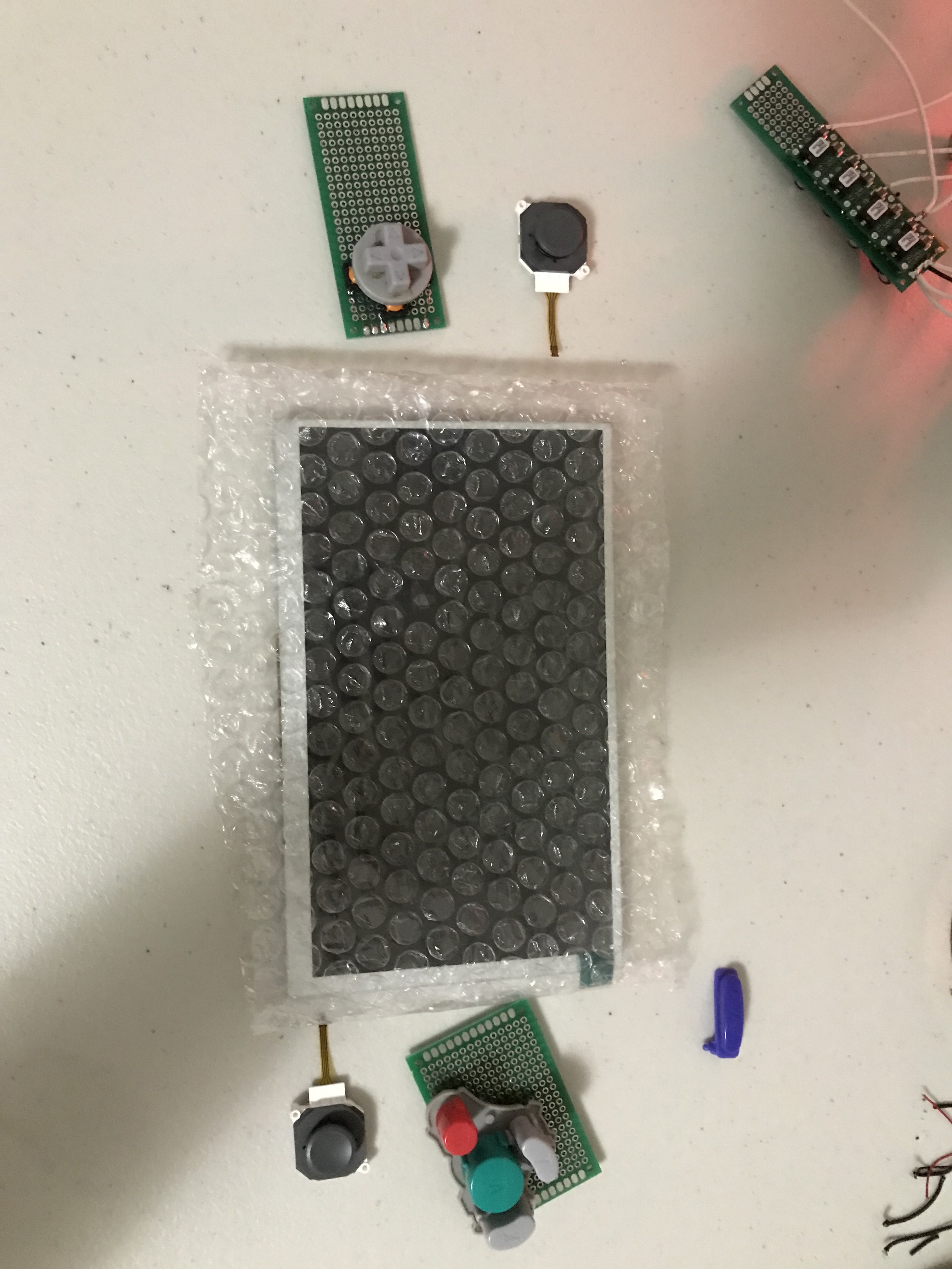
-A really really general idea of the screen/button layout. At the moment I am planning to use the GC buttons and maybe Dpad with 3DS sliders. I've got the buttons all hooked up to some perfboard with the ends I need to connect to soldered onto their own pads, that way I can wire it up easily and hopefully keep it a little cleaner.
Anyways, there's my work thus far. Feel free to give me any feedback or suggestions!
Thanks again to everyone being so helpful around here, I've wanted to do a portable ever since I saw a portable n64 guide back around 2010 but I'd never be able to get this far without this community! I'm excited to finish this one up and continue with updates then get started on some other projects as well.


") One day..
One day..