
- Joined
- Jan 28, 2016
- Messages
- 60
- Likes
- 661
The Definitive Wii Trimming Guide
Preface
Preface
Before proceeding further, you must first determine your board revision. Please use the Revision Identification Guide.
This guide is primarily designed to be used with CPU-40 boards and higher.
If your Wii is a 6-layer board, you will require the information in this guide as well as the 6-layer expansion guide.
Neither this guide nor the 6-layer expansion supports relocating the disc drive. With the utilities provided by modern softmodding, retaining the disc drive offers no significant benefit for the difficulty involved in soldering onto 0.1mm traces next to the GPU.
Softmodding your Wii
RVLoader is open source and designed specifically with trimmed motherboards in mind. It is currently the only supported softmodding solution on BitBuilt, and is required to be installed before trimming, to remove the requirements for Bluetooth, WiFi, and to enable the optional use of VGA. You should not try to use any other softmodding packs, as they are unsupported, and will not offer these critical features.
Remember: anything can go wrong once the board has been trimmed. It is vital to ensure that the console is fully functional and set up correctly beforehand, as this will establish a known working baseline condition to begin troubleshooting from.
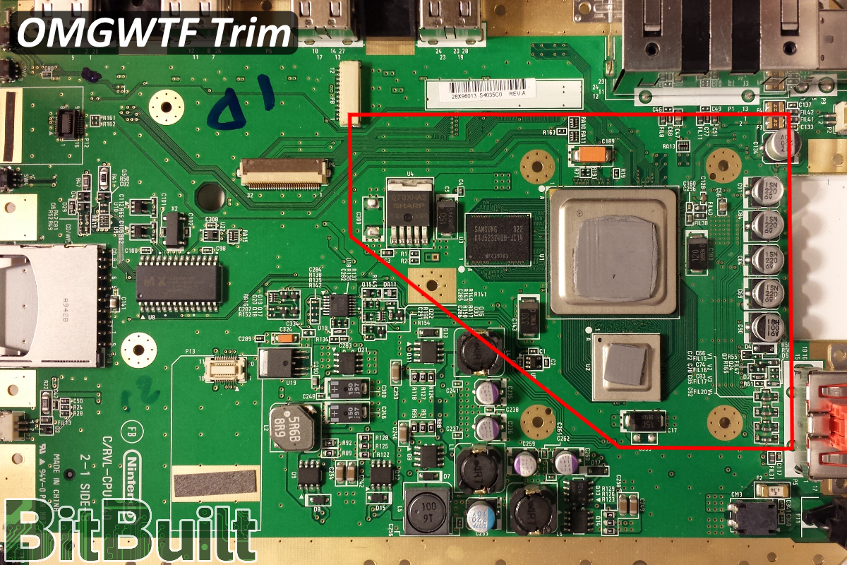
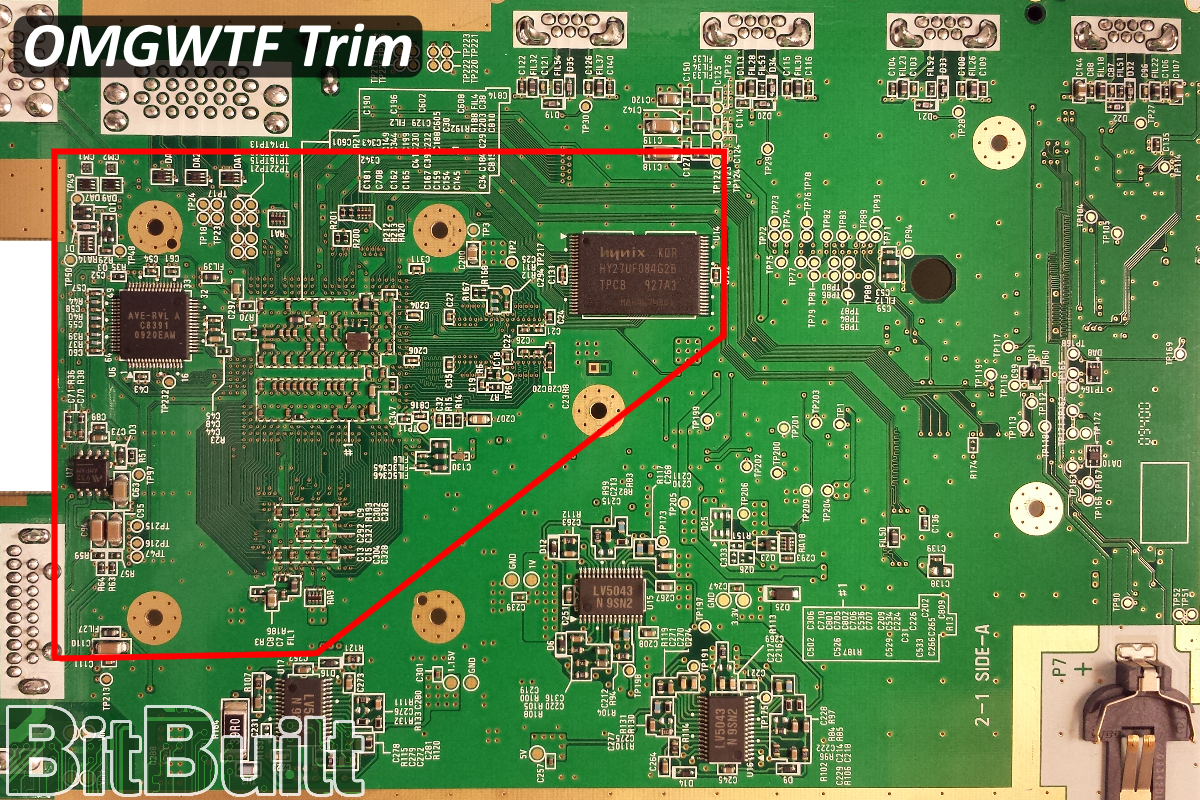
Designated trim
This entire guide has been designed around one specific trim. There are many things that will need to be reconnected before the console will boot up again. You are encouraged to read through the entire guide before trimming the motherboard, to understand everything that needs to be reconnected.
There are several things that can be relocated safely before trimming if you're choosing to use them, such as the Bluetooth module. It can be highly beneficial to do this before trimming, to verify that the attempted relocation was successful. For best results: perform one relocation at a time and test the system once the relocation is complete, before moving onto the next task. Note that having free-floating wires or components can sometimes make board trimming more difficult, so take it slow and always verify the integrity of your connections.
Once ready to trim, cover everything inside the red lines with masking tape, and then cut slightly outside the red line. It is safer to initially cut the board this way, and later sand down the board to meet the line. It is recommended to sand the edges of the board down with at least 600 grit sandpaper to ensure the internal layers are not bridged. You must also remove any cut or damaged components along the edge of the trim before attempting to power on the board, or you may end up with shorts that are likely to damage the system.
The large black component that the bottom left diagonal line cuts through can be removed with no problem.
Confirming the trim works
A trimmed unsoftmodded Wii motherboard has 4 requirements in order to boot. It must have:
- Bluetooth
- WiFi
- U10
- Custom regulators
Otherwise, the console will display the infamous black screen (or no signal at all).
However, if you have properly softmodded your console, this list can be reduced to as low as two requirements:
- U10
- Custom regulators
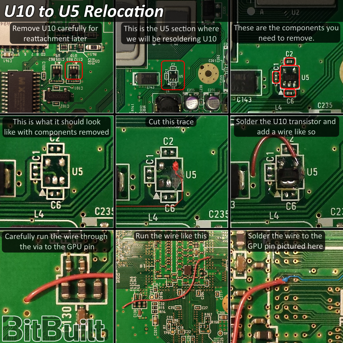
U10 relocation
In order for the Wii to boot up, the GPU must receive a delayed 3.3v signal connected to the via pictured below. The delayed signal is generated by the U10 IC located near the MX chip.
The easiest method of solving this problem is by removing the U5, a convenient component with the same footprint as the U10. It is located next to the GPU and CPU and is only used for the internal voltage regulators which are replaced by custom regulators.
Note: The U5 IC is NOT the same as the U10 IC, and must be removed for this to work. You must also remove the 3 capacitors (C1, C2, and C6) around U5 as well.
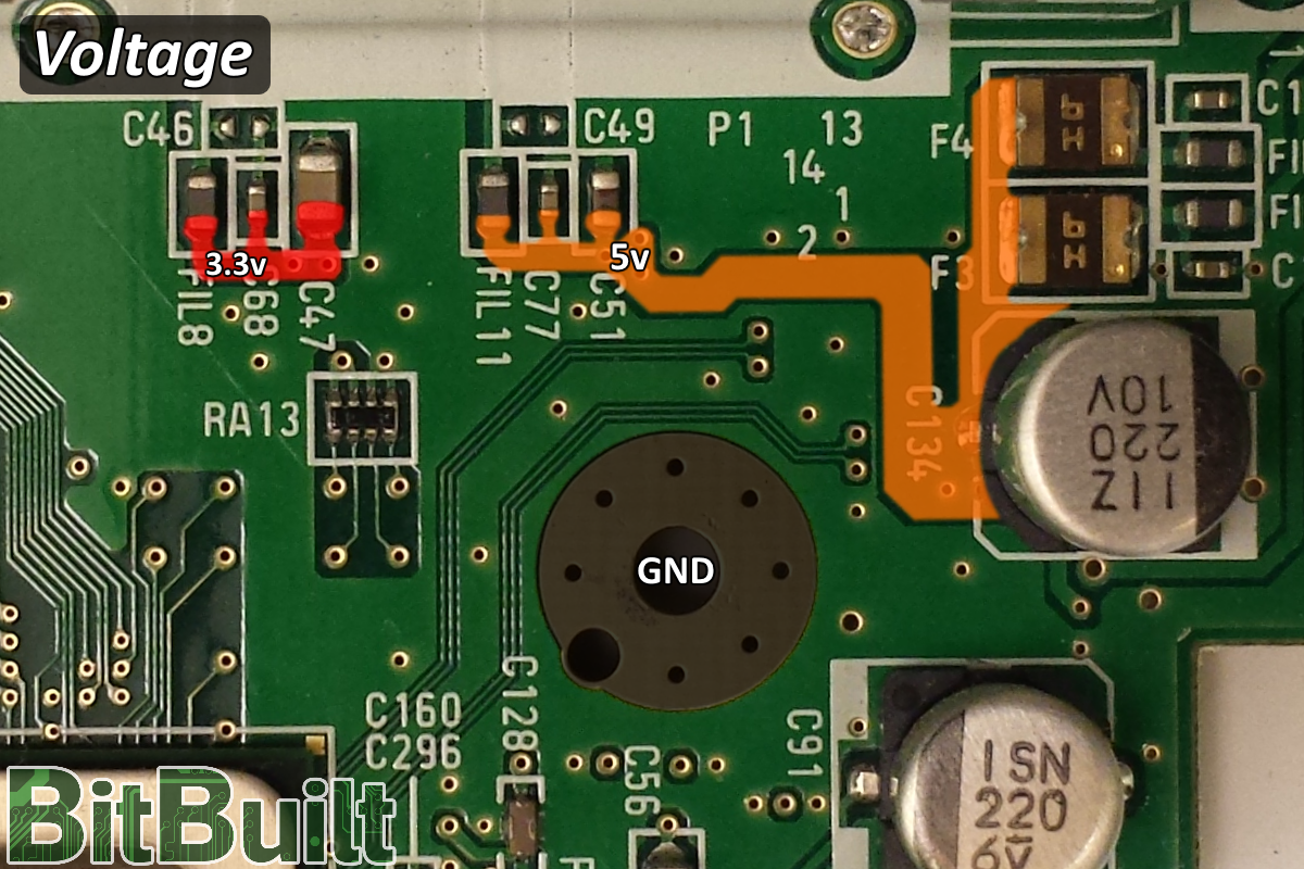
Custom regulators
In order for custom regulators to work properly, all onboard regulator components need to be removed. It is recommended to trim the motherboard first as shown at the start of this guide to remove them before connecting the custom regulators, as the onboard regulators will cause issues and the Wii will not boot.
You can read more about custom regulators here. As a general rule, you should aim to use stranded wire for connecting voltage to the motherboard, using a thicker gauge of wire for your primary voltage rails going into the board, and thinner wire for peripherals like the Bluetooth module. Solid core wire is not recommended.
Note: The 1v and 1.15v lines cannot be powered on the same voltage and must be connected to dedicated 1v and 1.15v regulators.
5v is not required for the board to boot. It is only used for USB, GameCube controller rumble, and the memory card slots. Consider connecting this voltage directly from the regulator to these peripherals.
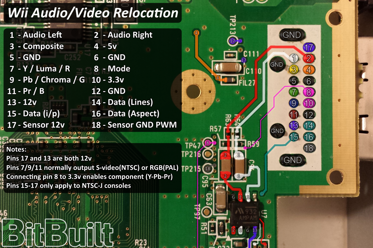
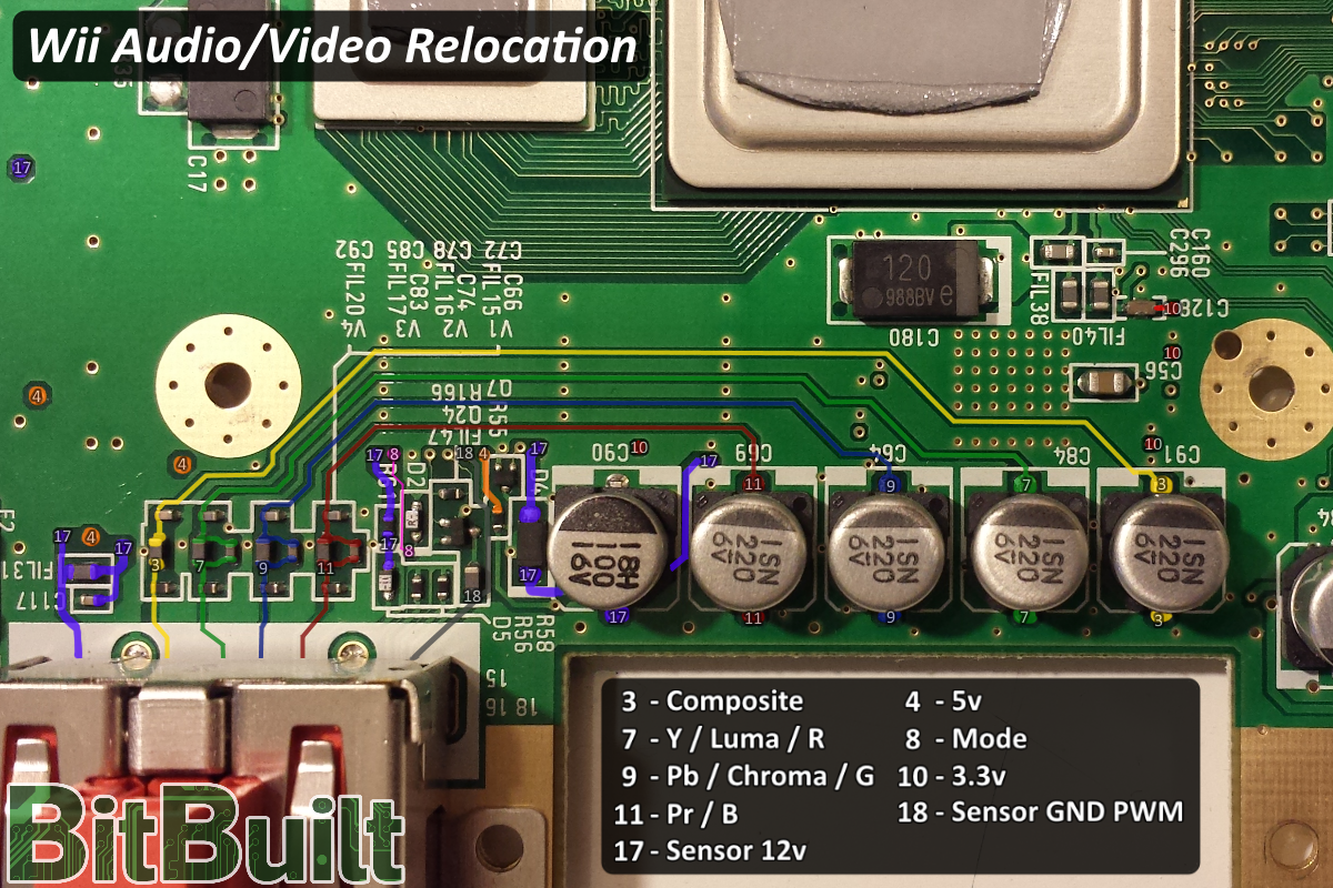
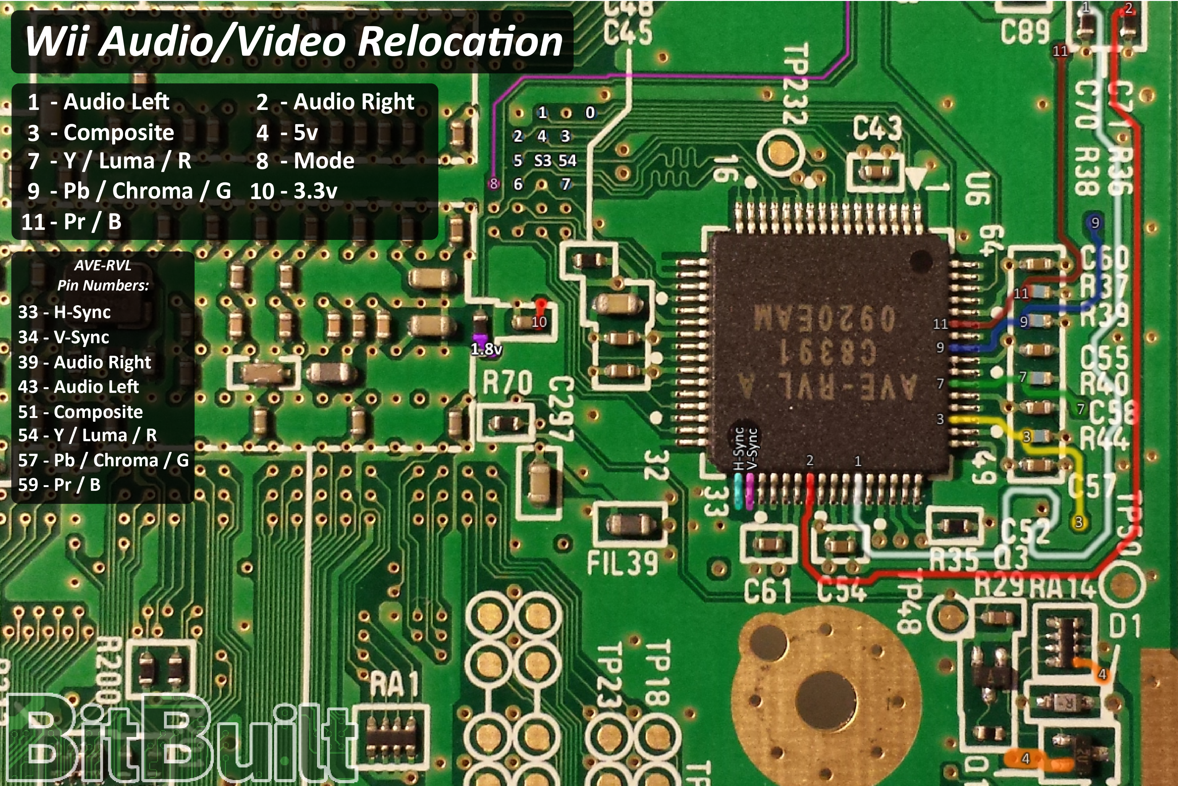
Audio/Video
There are multiple alternate points to connect audio and video to.
In order to use YPbPr you must wire Mode to 3.3v. This is also true when using VGA, which must be enabled through softmodding.
Additionally, when using VGA, pay special attention to the pin numbers listed in the legend: the red, green, and blue pin coloration reflects the native YPbPr, not VGA.
H-Sync and V-Sync must also be directly connected to the AVE-RVL, as no other connection points are available.
“Data” pins are only required for NTSC-J consoles.
When using custom regulators, the onboard audio preamp does not get 12v. You can either connect your primary voltage input to the 12v pins on the audio preamp, or use the alternate audio points located on the encoder or the bottom of the audio preamp(marked 1 and 2 on the very bottom of the first image below.)
USB
USB is required for homebrew and launching games. You should directly supply 5v from your regulator to the USB port, as 5v does not need to be supplied to the Wii itself.
It is recommended to connect the data lines to the CM1 and CM2 components for added safety, especially if using an external USB port; as a bad drive or device has potential to damage the USB data lines going to the GPU.
Lines 3 and 7 (shown in green) are D+. Lines 2 and 6 (shown in gray) are D-.
Each set of USB data lines are a differential pair, and as such should be twisted together in a helix formation to reduce interference. Only twist 2 with 3, and 6 with 7. This will greatly increase stability and is highly recommended. Instability can manifest as random crashes due to failures to read from the drive, or the drive failing to work at all.

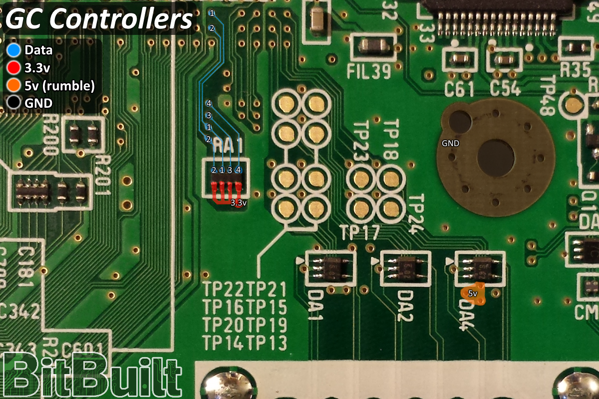
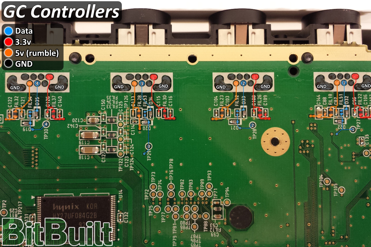
GameCube controllers
GameCube controllers can be used for virtual console, as well as homebrew and standard GameCube games. The controllers only need 3.3v, data, and GND to function properly. 5v is not required, as it is only used for rumble.
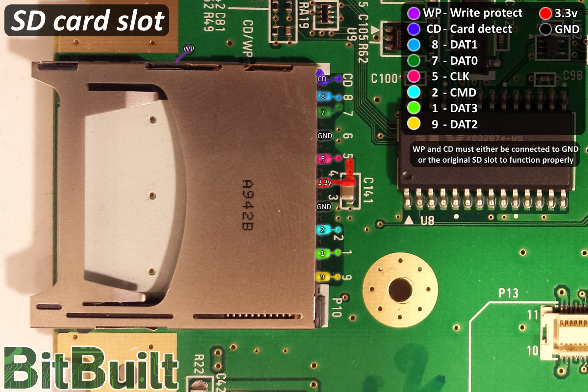
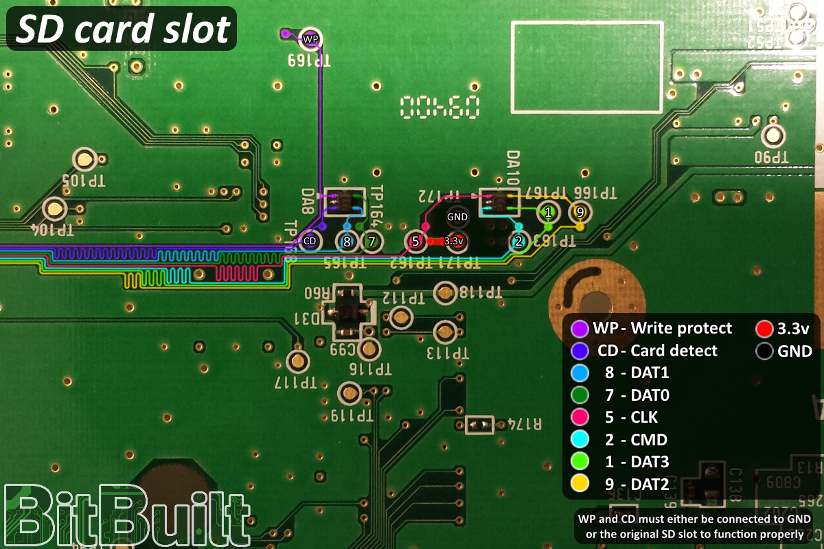
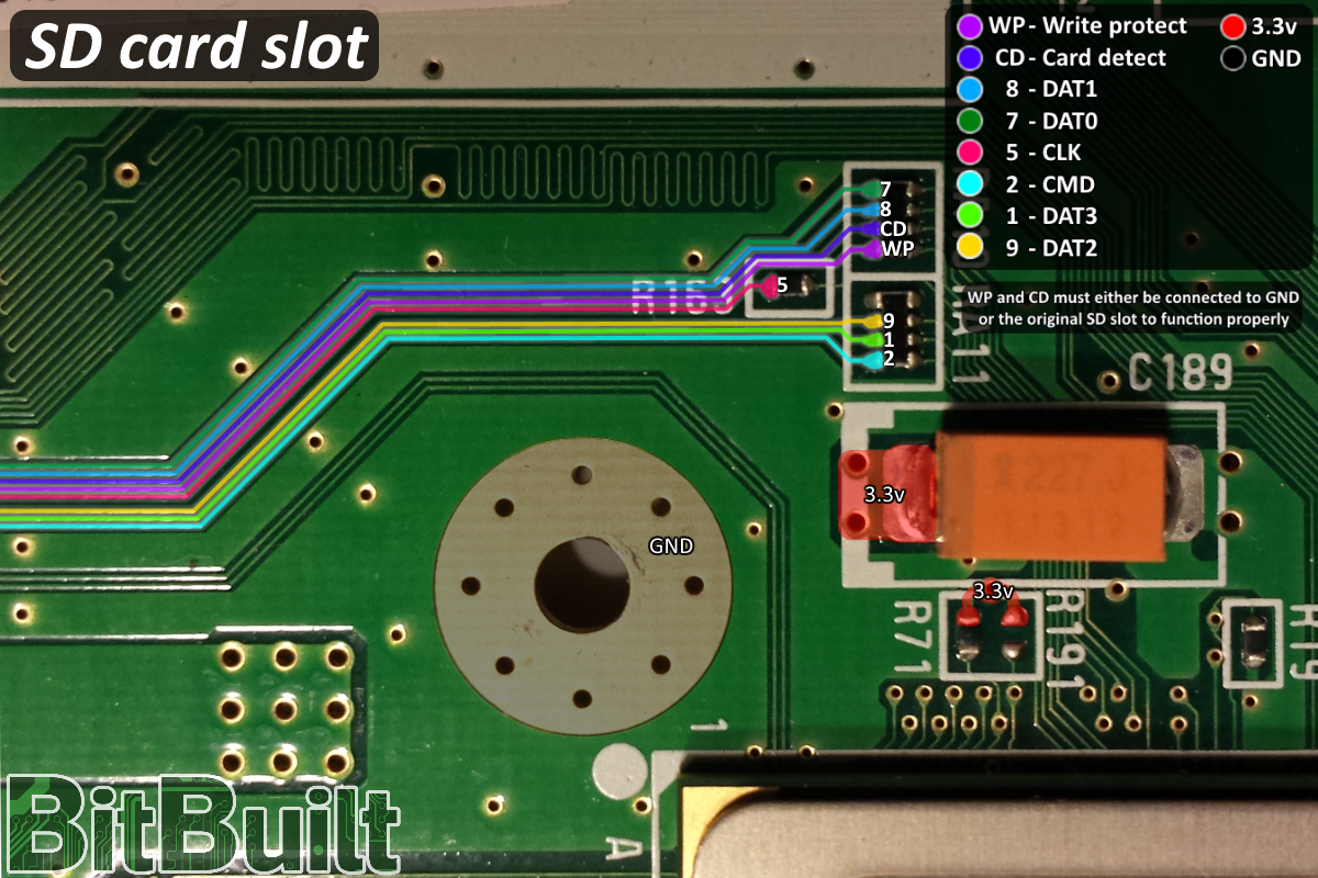
SD card slot
The SD card slot is optional, and can be used for additional homebrew and save data. When trimming the board, it is advised to cut out and reuse the SD card slot. This makes it easier to mount, and you can use the test points on the bottom of the board, which are shown below.
If using a third party SD card slot, reference your schematic to determine the correct way to connect CD and WP. If your slot lacks that functionality, you can directly connect those two pins on the Wii to GND.
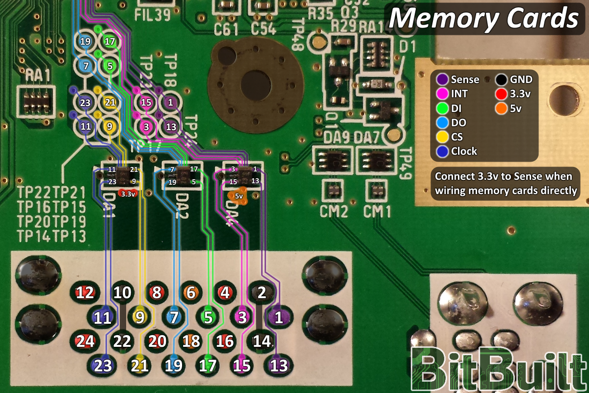
GameCube memory cards
Softmodding supports virtual memory cards, thereby eliminating the need to use physical memory cards. However, the original slots can be reconnected anyways in order to manage save data from a physical card instead. This can be very useful when transferring data between consoles.
5v is not strictly required, as it is only used for specific peripherals such as the GameCube microphone.
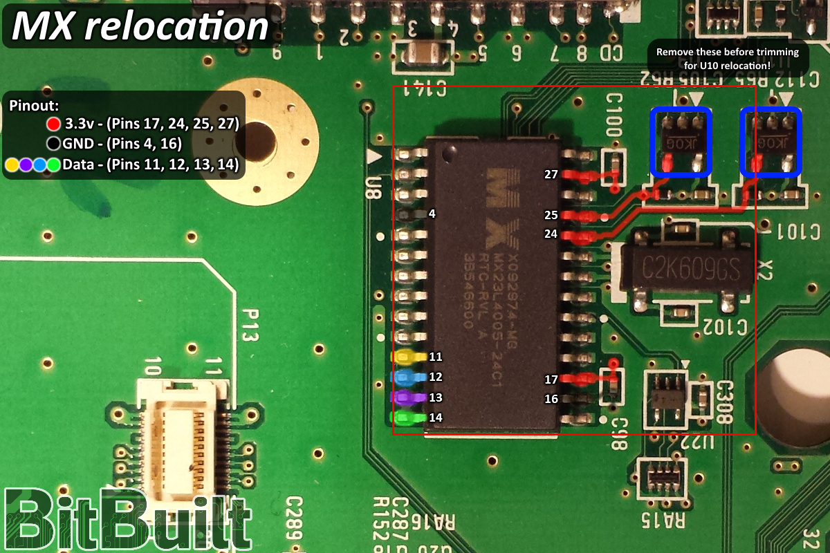
MX chip and Reset Button
The MX chip serves various functions on the Wii, however by eliminating the disc drive and using custom regulators, only two of its functions remain relevant: GameCube font data and Real Time Clock (RTC). While modern softmodding solutions have removed the need for the font data, there is presently no solution available for restoring RTC functionality aside from relocating the MX chip.
As the MX chip has a variety of supporting components, it is recommended to cut this section of the board out as shown.
After reconnecting 3.3v, GND, and the data lines to the Wii, all that needs to be added for proper RTC functionality is a 3v lithium button battery. The positive terminal of this battery should be connected to the B+ pad shown in the second MX Relocation diagram, and the negative terminal to any nearby ground location.
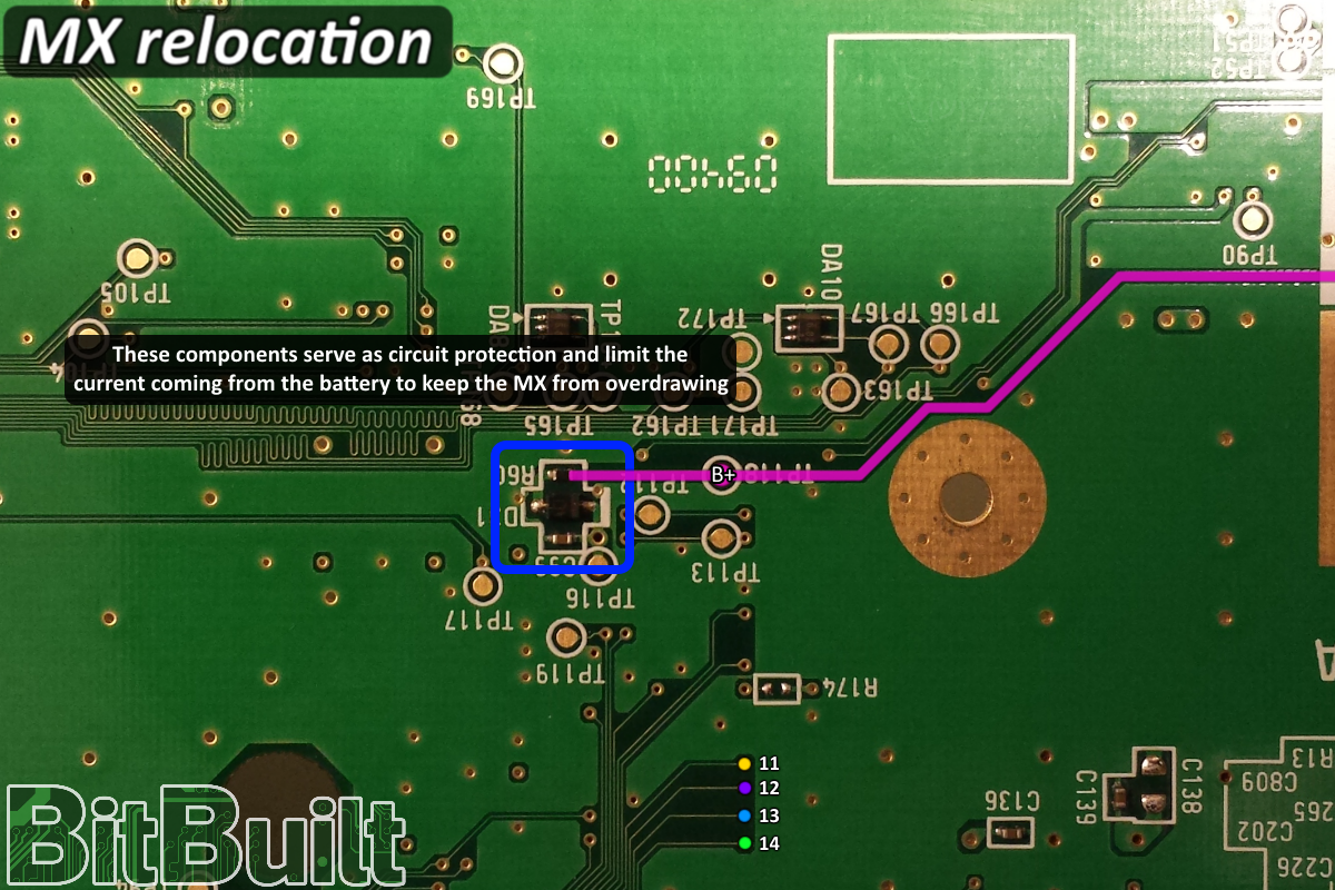
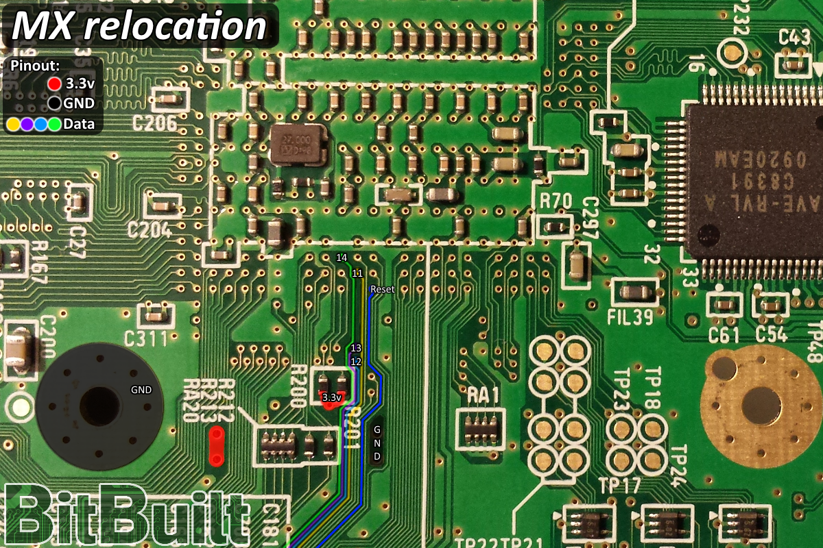
Note: To activate the reset button function, temporarily connect the pin marked "Reset" to GND.
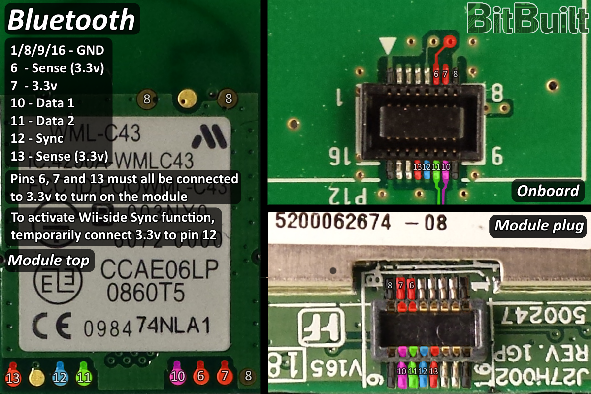
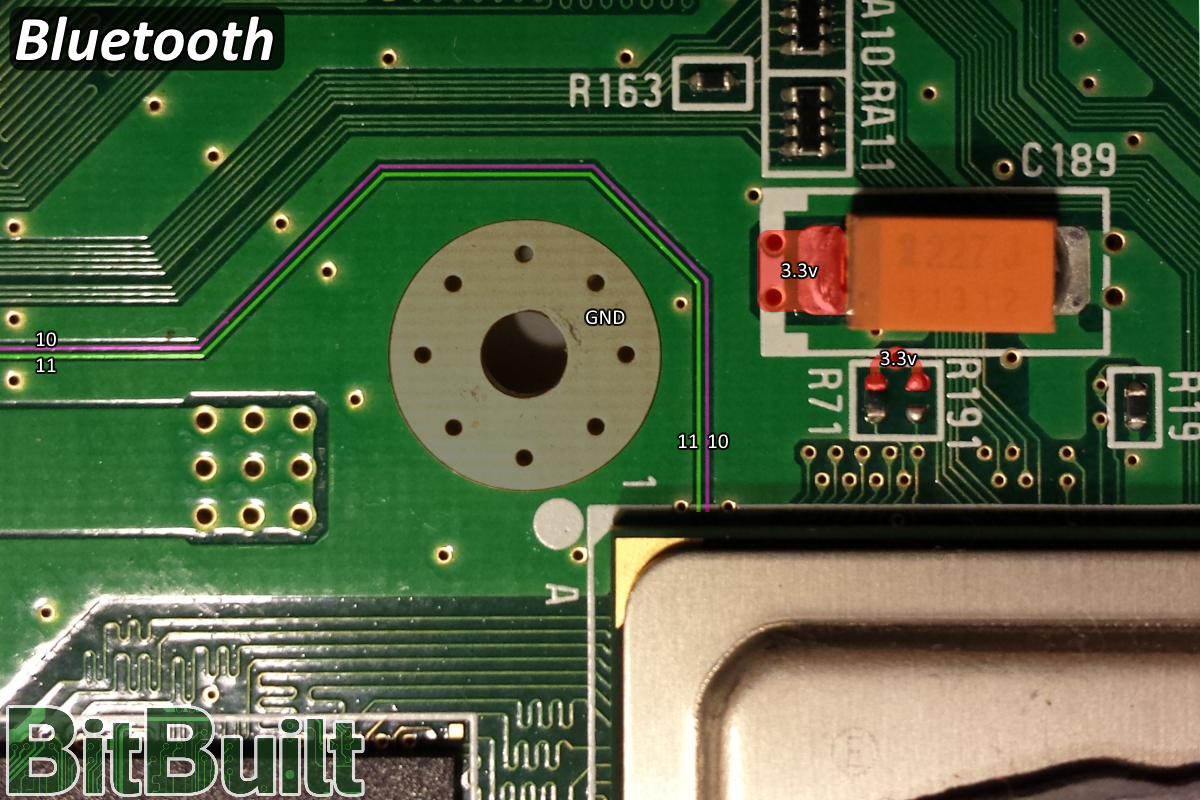
Bluetooth
If you are choosing to keep it, the Bluetooth module can be the most difficult relocation on the entire board. It has a unique design in that the two required data traces have no convenient relocation points, instead going straight from the resistors near the plug all the way to pads underneath the GPU without using any vias. This means the only way to reconnect the module is to scratch some of the solder mask off of the 0.1mm traces to provide our own points to solder to. This is commonly done with 30AWG solid core enameled magnet wire, but a higher gauge like 32AWG can be easier for some users. As these lines are also a differential pair, they should be twisted together in a helix formation in order to help mitigate interference and ensure a quality connection.
It's also recommended to securely mount your Bluetooth module beforehand in some way to reduce the risk of breaking the delicate solder joints or otherwise damaging the traces. Thin, double sided tape is good for this purpose, as using epoxy or glue can create a problem if the relocation needs to be changed later.
If these test pads are not immediately visible on the Bluetooth module that came with your Wii, the sticker may be covering them and should be carefully lifted to expose the pads. All modules have these test pads.
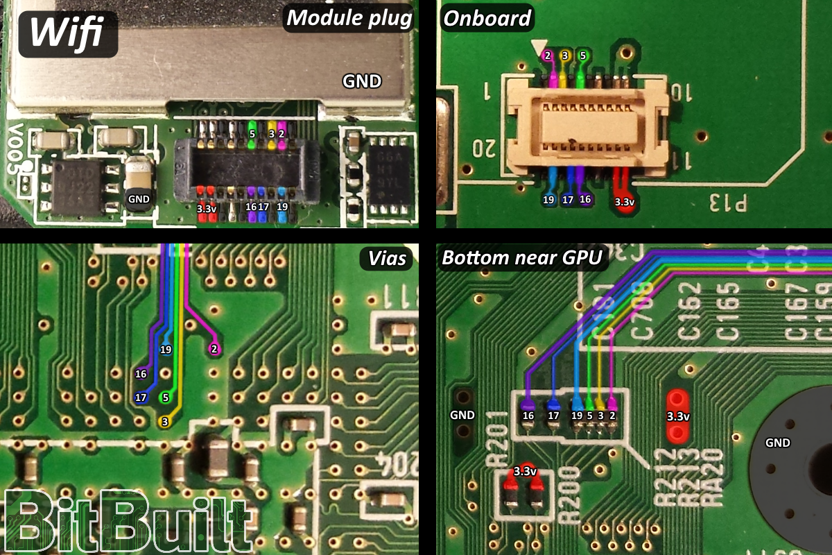
WiFi
WiFi is wired directly to resistors on the bottom side of the motherboard. It is recommended to use at least 30AWG magnet wire for the data lines, as the pins are very close together.
It is CRITICAL that the 6 data wires are as short as possible.
Postface
This guide is the culmination of months of research by a large group of individuals. However, since we are only human there is a chance that there may be mistakes. If you find something, please post it somewhere and tag @ShockSlayer as he has all of the original project files for the images and can make updates if necessary. Thanks for reading!
ShockSlayer - established the compendium and information standards, tested everything and accomplished the first OMGWTF trim and made all images in this guide
Cheese - initially removing mx chip and research, bluetooth and other misc testing, misc compendium work, guide work
Bentomo - sanding and scanning the compendium board scans, most notably down to the internal voltage layer for essentially full transparency of the board layout
Shank - documentation on board revisions, overwhelming majority of compendium work, assorted testing and initial reaching out to various members of the group
Gman - misc compendium work, testing custom regulators, original documentation, testing and inspiration
Special thanks
JacksonS - full component documentation
Ashen - for the OMGWTF name, we love you come back to portablizing
Noah - for providing BitBuilt in its early years
Changelog
04-28-16 - Added alternate points to WiFi diagram. -ShockSlayer
07-03-16 - Updated to reflect PortablizeMii and the current direction of Wii portablizing. -ShockSlayer
07-14-16 - Updated some terminology. -ShockSlayer
12-18-16 - Updated to reflect 6 layer boards and new revision guide. -ShockSlayer
03-29-17 - Updated MX chip trim lines and updated relocation points. -ShockSlayer
04-23-17 - Added some text about using masking tape and the unneeded inductor. -ShockSlayer/Aurelio
11-05-21 - Finally replaced PortablizeMii with RVLoader, and added link -Cheese
07-05-22 - Cleaned up BB code tags rendering on post, slight wording change in special thanks to avoid confusion on if Noah currently owns BB -CrashBash
02-25-23 - Added text in the USB section to designate the D+ and D- colours and explain the essential nature of twisting the data wires -Stitches
05-07-23 - Clarified the requirement of the Bluetooth relocation with RVLoader -Aurelio
06-05-23 - Added 1.8v locations to the main voltage diagram. Added a basic explanation for restoring the RTC battery to the MX section. Added a note to the Audio/Video section to warn VGA mod users of the yPbPr graphical colours not aligning with RGB video. Adjusted the wording of the trimming warning and added a reminder to remove damaged components along the trim edge. -Stitches
08-14-23 - Revised the Bluetooth section text to advise twisting the BT data wires together for interference mitigation at Shank's request, and removed outdated text saying that the BT module is still a required relocation. -Stitches
08-27-23 - Added a basic explanation about using the correct wire types for each pupose to the voltage section -Stitches
11-27-23 - Removed bloat, reorganized a few things, removed extra dependencies, refined some language. -ShockSlayer
Last edited by a moderator: