- Joined
- May 30, 2017
- Messages
- 41
- Likes
- 30
Hi all,
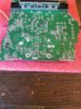
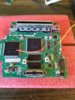
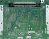
Is the N64 board reduction referenced here:
https://bitbuilt.net/forums/index.php?threads/trimming-your-n64-revs-1-4.52/
Specific to a CPU revision? The pictures have NUS-CPU-004, but will the full reduction work on the other CPU revisions 001-003?
Thanks
Is the N64 board reduction referenced here:
https://bitbuilt.net/forums/index.php?threads/trimming-your-n64-revs-1-4.52/
Specific to a CPU revision? The pictures have NUS-CPU-004, but will the full reduction work on the other CPU revisions 001-003?
Thanks