Worklog PWP2 Worklog (PiiWii Pocket 2)

Shank

Moderator
Staff member
.
.
Joined
Jan 31, 2016
Messages
1,287
Likes
2,726
Portables
6
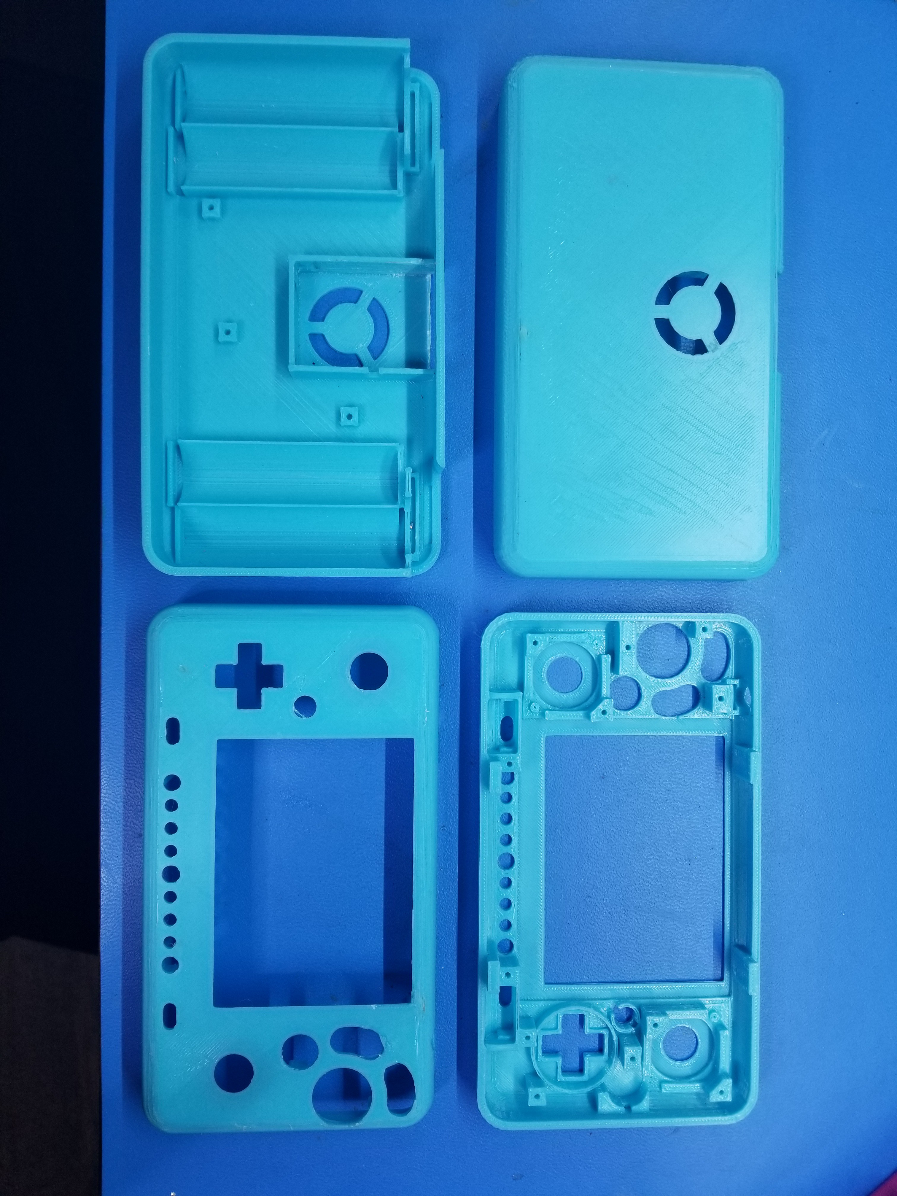
The PiiWii pocket was the first portable I saw to the end. I loved the case and ergonomics, but the internals were pretty awful. I've been working on a followup for a few months with the goal of keeping the same external appearance. However, I plan on reworking the internals using everything I have learned in the 2 years since making the original. Hopefully these internals will be something I can be proud of. I finally have something to show, so its time for a worklog.

Planned features:
-Similar appearance to the PiiWii Pocket
-3D printed Case
-Screw posts
-99% glue free
-Custom trim with partial NAND relocation
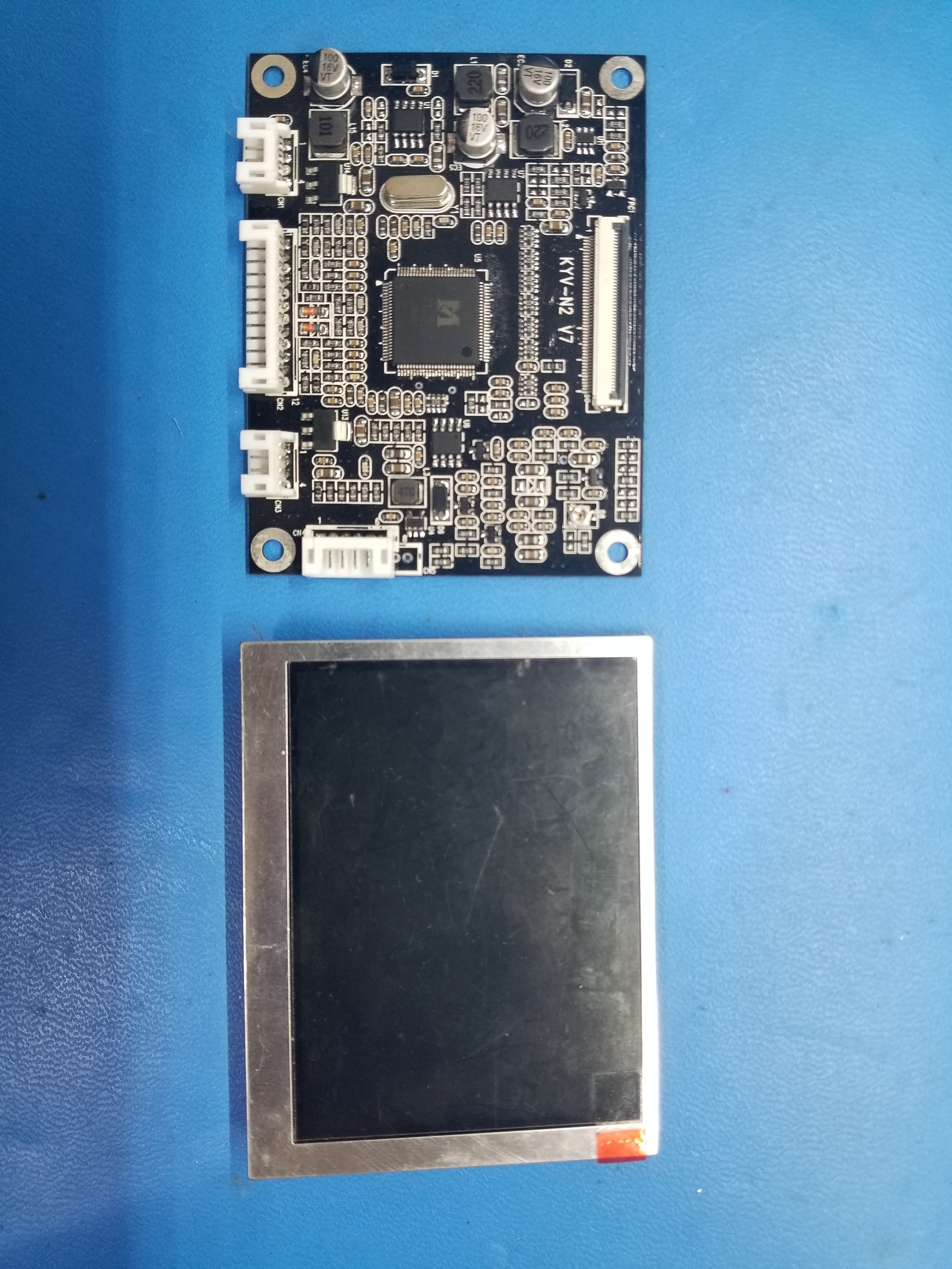
-3.5" 640*480 VGA LCD (4x the resolution of the original)
-Same face buttons, but improved start and shoulder buttons
-3DS Sliders
-4 18650s
-7mm wider, but much thinner (smaller overall)
-Dual USB ports
-Rumble Motor
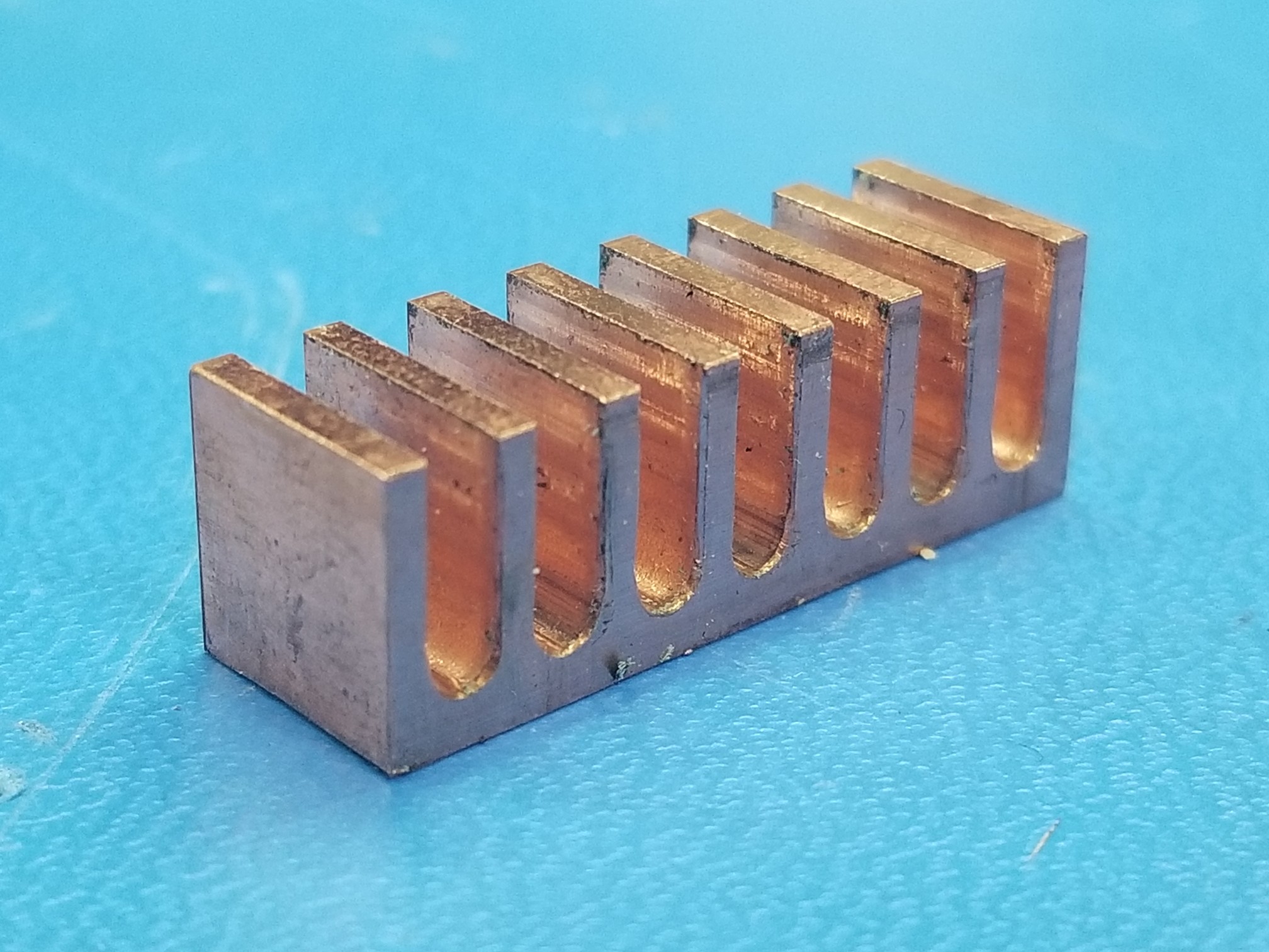
-Custom milled copper heatsink
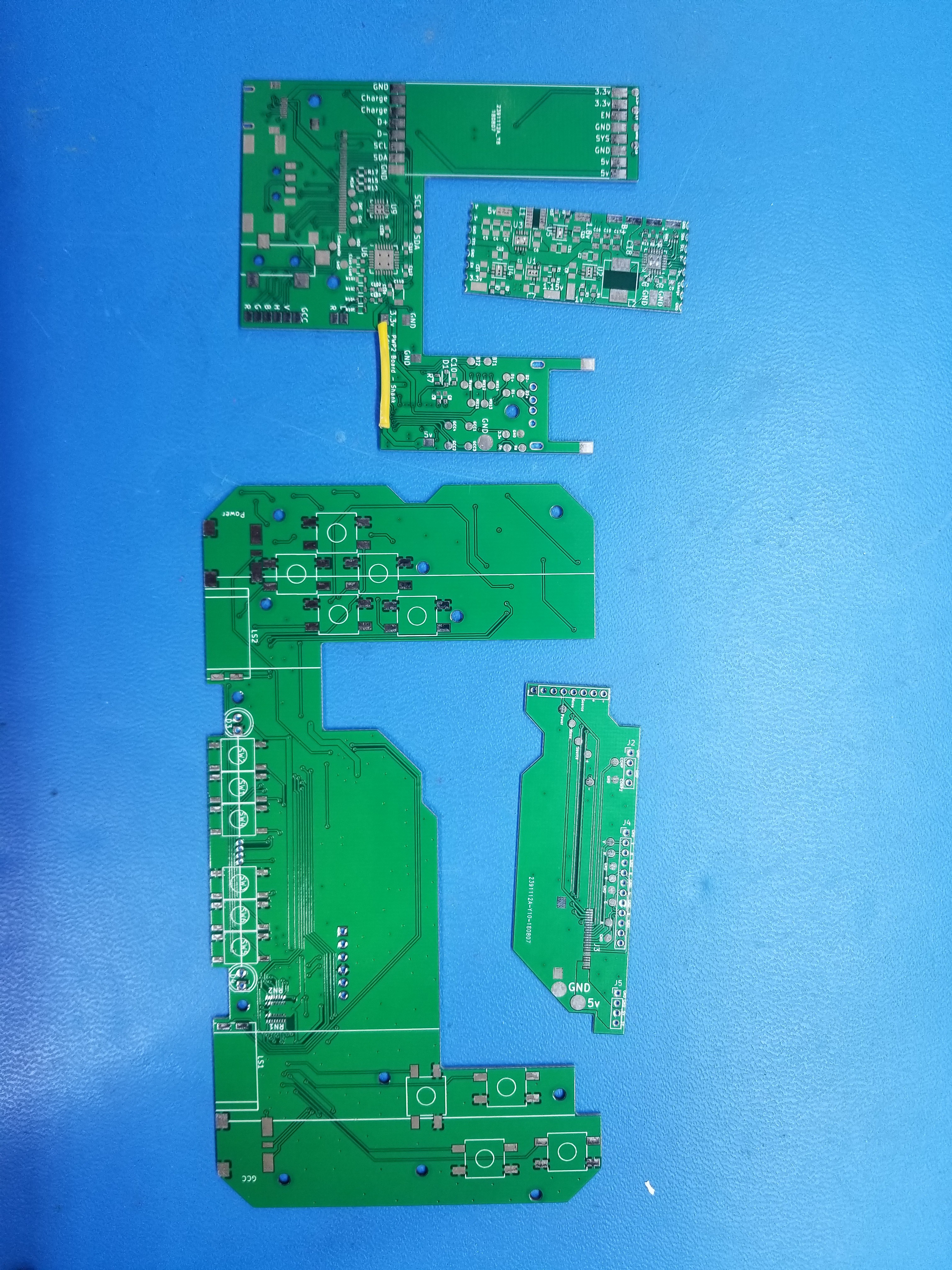
-Custom PCBs Galore, including controller, audio amp, regs, and battery management
-Secret bonus feature to be revealed


Here's some pictures. More to come.
20180813_134316.jpg

20180813_133909.jpg

20180813_134110.jpg

20180813_134548.jpg

Edit: Uploaded higher res photos. Accidentally uploaded the thumbnails before. Oops.
 
Last edited:

GingerOfOz

no wario
Staff member
.
.
2020 2nd Place Winner
2022 3rd Place Winner
Joined
Dec 16, 2016
Messages
1,122
Likes
2,710
Location
The Oregon Wildlands
Portables
just so many i am so cool
That all in one board for the front looks pretty slick. How much did something that size run you?
 

Shank

Moderator
Staff member
.
.
Joined
Jan 31, 2016
Messages
1,287
Likes
2,726
Portables
6
Total for 10 of each PCB, stencils, and shipping was about $70 through JLCPCB.
 

BocuD

.
Joined
Jul 21, 2016
Messages
468
Likes
606
Location
The Netherlands
Portables
3
Hot damn this looks nice
Is the entire portable (aside from the wii and lcd driver) one pcb or something?
I really can't wait to see it done..
 

BocuD

.
Joined
Jul 21, 2016
Messages
468
Likes
606
Location
The Netherlands
Portables
3
if you change the 'W' to 'S' it turns into the 'PSP2' :rothink:
He just has to make the pcbs blue and a bit more dense lol.. They look about as professional as Sony's
 

Shank

Moderator
Staff member
.
.
Joined
Jan 31, 2016
Messages
1,287
Likes
2,726
Portables
6
Got the remaining parts in the mail. Was able to trim a board and use it as a test dummy. Had trouble with the regulator module having a 5.5khz humm, which was fixed by adding a .1uf and a .01uf capacitor stacked on the battery management output caps (c17 and c19 specifically.) Next circuit board batch will have pads for these caps.
20180823_133810.jpg

I fixed up the soldering on U3 and was able to get the board to boot on a single cell. The reg module board successfully charges cells off any voltage above 4.5v and outputs every voltage needed to run the Wii, including 1.8v.
20180823_222556.jpg

While I was able to rig it to power on the console, most functions require a microcontroller to work. It is controlled by the microcontroller placed on the U-Shaped board it solders onto. I've nicknamed this board the U-Board. I assembled most of the U board, and soldered in the power module. The U-Board also has all the ports, audio amp (essentially a clone of the amp circuit by @JacksonS ), MX chip and its components, BlueTooth module, RTC battery, and a few other goodies.
20180824_013059.jpg

Unfortunately, I messed up my design on the U-Board and didn't set a 3.3v fill zone to be a higher priority than the gnd plane. So I have a short from 3.3v to gnd...
20180824_005552.jpg

Well... I HAD one, but now I don't, thanks to razor buddy. Looks like Bluetooth is gonna have some wires on this version. Bummer. I'll fix it on the next one though.

Other than that, everything is working much better than I expected. Given this is my first major custom PCB, I expected to screw up a lot more. Shoutouts to @Gman for helping me suck less. I'm really excited for the project, and should have a lot more to share in the near future.
 

Stitches

2 and a Half Dollarydoos
Staff member
.
.
Joined
Feb 5, 2017
Messages
3,847
Likes
3,024
Location
Banana Bender Land, Australia
Portables
6
Got the remaining parts in the mail. Was able to trim a board and use it as a test dummy. Had trouble with the regulator module having a 5.5khz humm, which was fixed by adding a .1uf and a .01uf capacitor stacked on the battery management output caps (c17 and c19 specifically.) Next circuit board batch will have pads for these caps.
View attachment 7082
I fixed up the soldering on U3 and was able to get the board to boot on a single cell. The reg module board successfully charges cells off any voltage above 4.5v and outputs every voltage needed to run the Wii, including 1.8v.
View attachment 7081
While I was able to rig it to power on the console, most functions require a microcontroller to work. It is controlled by the microcontroller placed on the U-Shaped board it solders onto. I've nicknamed this board the U-Board. I assembled most of the U board, and soldered in the power module. The U-Board also has all the ports, audio amp (essentially a clone of the amp circuit by @JacksonS ), MX chip and its components, BlueTooth module, RTC battery, and a few other goodies.
View attachment 7084
Unfortunately, I messed up my design on the U-Board and didn't set a 3.3v fill zone to be a higher priority than the gnd plane. So I have a short from 3.3v to gnd...
View attachment 7085
Well... I HAD one, but now I don't, thanks to razor buddy. Looks like Bluetooth is gonna have some wires on this version. Bummer. I'll fix it on the next one though.

Other than that, everything is working much better than I expected. Given this is my first major custom PCB, I expected to screw up a lot more. Shoutouts to @Gman for helping me suck less. I'm really excited for the project, and should have a lot more to share in the near future.
Are there components on both sides of that reg board? I only see two ICs for the 5 voltages.
 

Shank

Moderator
Staff member
.
.
Joined
Jan 31, 2016
Messages
1,287
Likes
2,726
Portables
6
Minor update. I realized I never showed the other side of the U-Board. I soldered the remaining components on it tonight as well. Still gotta clean the flux off though.
20180825_030056.jpg

Here we have a connector and place for the Bluetooth module, mx chip, RTC oscillator crystal, battery tray and pinhole switches for reset and LCD source. These are just tact switches that don't extrude from the case, so you need to poke a pin through a hole to press them. These switches will mostly be used for troubleshooting, so I don't want to accidentally hit them during gameplay. Reset is for priiloader troubleshooting, while LCD channel will let me switch to composite to troubleshoot video.

I did find PCB mistake #3: The MX chip's footprint is wrong! I was able to make it work using some hot air schenanigins to get some smooth solder fillets behind the legs to the pads, but I want to fix it on the next version. It's a solid connection, but it was gimcky to make it work.

I thought I had a mistake #4 of having 3.3v shorted to the charging line, but the culprit was bad soldering. A bit of flux and a touch-up and the issue was gone.


Are there components on both sides of that reg board? I only see two ICs for the 5 voltages.
There are no components on the other side of the board. It is soldered straight onto the U-board. U1, U2, U4 and U5 on the power module are regulators that have built in inductance. Rather than being in a normal IC package, the chip is just on a substrate that has an inductor soldered on top, similar to how some processors have capacitors soldered on them under the heat spreaders.
 

Shank

Moderator
Staff member
.
.
Joined
Jan 31, 2016
Messages
1,287
Likes
2,726
Portables
6
Before class today I was able to solder together the front half of the controller board. The main feature of the controller board has a GC+ on it, as well as all the buttons, 3ds slider ffc connectors, and solder pads for rumble. It also has the center RGB LED, 2 IR LEDs, contact pads for the spring contact speakers, power switch, controller switch, and FFC connectors to connect to the two other boards used in this portable. Either 3.3v or 5v can be used on the rumble motors by soldering one of the two jumpers to the right of the 50 pin FFC. Credits of all those I have to thank are concealed: I'll save the credits for the end ;)
20180828_160557.jpg

Next we have the front half, which I just finished this evening. I still have a few other parts to add, but I'm waiting to do measurements in respect to other parts in the case so they all extrude just the right amount. The twin 8 resistor arrays I ordered was the wrong footprint. Fortunately, I had some 4 resistor arrays with the same pitch and values, so I made them work.
20180829_001716.jpg

I wasn't able to find SMD tact switches of the popular orange squishy tacts, so I made my own.
20180829_002108.jpg

Lots of progress, but lots to go.
 
Top