- Joined
- Feb 25, 2016
- Messages
- 1,437
- Likes
- 2,887
Everyone else has started a worklog but me, I guess it's time to show my cards. name is subject to change.
I don't have much physical progress done yet. I've been working on the solidworks models since April and the custom pcbs the last few weeks. The design has been highly optimized for 3D printing so it only needs to print with a few supports. I may make a few more edits internally, but the model is pretty close to a functional piece.
This portable would not be possible without my PS2 trimming initiative that started back in January. My recent learning of pcb design will play a large role in the assembly.
The front face:
PSP action buttons, PS Vita dpad, and mini joysticks (none of that slider stuff going on). A 5" 4:3 screen with stereo speakers.

The top:
Custom R1/R2 and L1/L2. Micro usb for convenient charging (there will be another way of charging for max charging current). Tact switch for on/off.
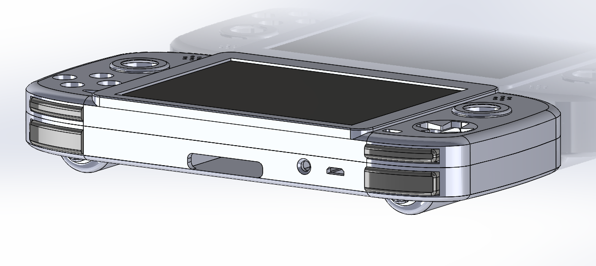
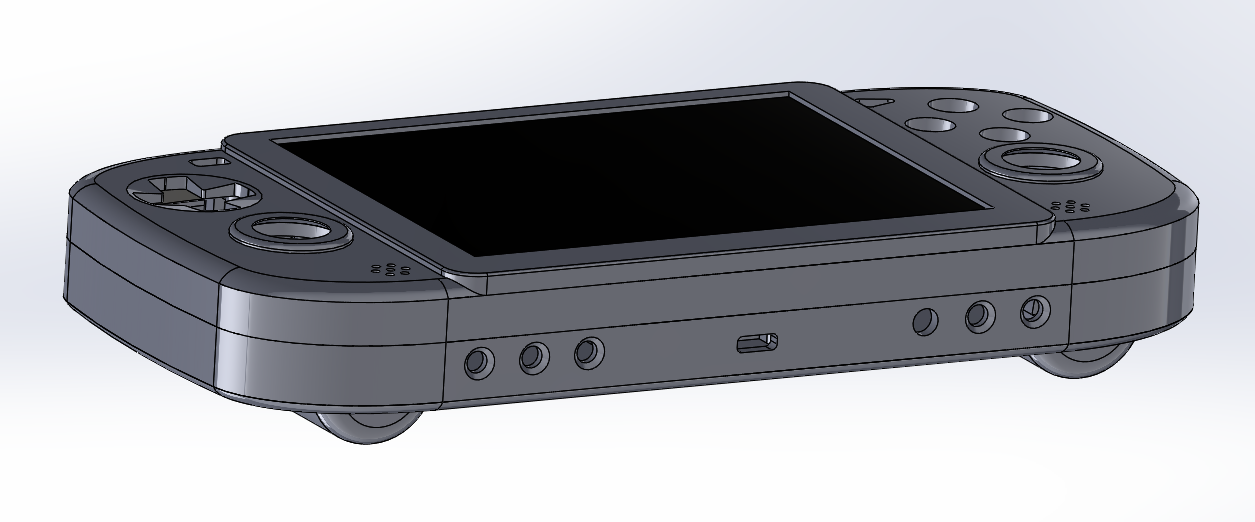
The bottom:
Screen controls, USB-C, headphone jack, volume +/-.
The back:
Removable battery covers for some thinness magic and swapping 18650s. The main portable body should be a hair under an inch (subject to change less or more depending on how part placement tests go). The jewel piece on the back is an idea I'm playing with, I may make some changes or just get rid of it, if it doesn't come out well.

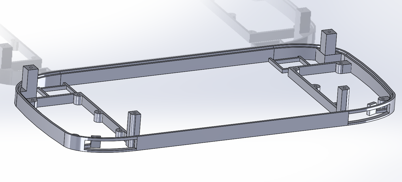
The side brackets:
The portable prints in 6 parts. This was tricky because all the extrusions on the top/bottom brackets need to be connected together.
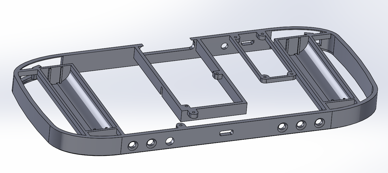
The battery covers:
There is a "lip" on one end which slides into the portable, the other end is tightened into a trapped nut inside the case. These covers are in the ideal placement for nice feeling grips when holding the portable.

There's a lot going on in the inner workings of the portable which I will be testing soon. I haven't decided on a color yet, I was thinking either a metallic red, or black, or something else. For time management: I give myself another month for design changes/testing, and the last few weeks for making the case nice and assembling it. There's a lot of work still to be done but I should be able to finish in time hopefully.
I don't have much physical progress done yet. I've been working on the solidworks models since April and the custom pcbs the last few weeks. The design has been highly optimized for 3D printing so it only needs to print with a few supports. I may make a few more edits internally, but the model is pretty close to a functional piece.
This portable would not be possible without my PS2 trimming initiative that started back in January. My recent learning of pcb design will play a large role in the assembly.
The front face:
PSP action buttons, PS Vita dpad, and mini joysticks (none of that slider stuff going on). A 5" 4:3 screen with stereo speakers.
The top:
Custom R1/R2 and L1/L2. Micro usb for convenient charging (there will be another way of charging for max charging current). Tact switch for on/off.
The bottom:
Screen controls, USB-C, headphone jack, volume +/-.
The back:
Removable battery covers for some thinness magic and swapping 18650s. The main portable body should be a hair under an inch (subject to change less or more depending on how part placement tests go). The jewel piece on the back is an idea I'm playing with, I may make some changes or just get rid of it, if it doesn't come out well.
The side brackets:
The portable prints in 6 parts. This was tricky because all the extrusions on the top/bottom brackets need to be connected together.
The battery covers:
There is a "lip" on one end which slides into the portable, the other end is tightened into a trapped nut inside the case. These covers are in the ideal placement for nice feeling grips when holding the portable.
There's a lot going on in the inner workings of the portable which I will be testing soon. I haven't decided on a color yet, I was thinking either a metallic red, or black, or something else. For time management: I give myself another month for design changes/testing, and the last few weeks for making the case nice and assembling it. There's a lot of work still to be done but I should be able to finish in time hopefully.