- Joined
- Aug 7, 2023
- Messages
- 14
- Likes
- 5
The Problem:
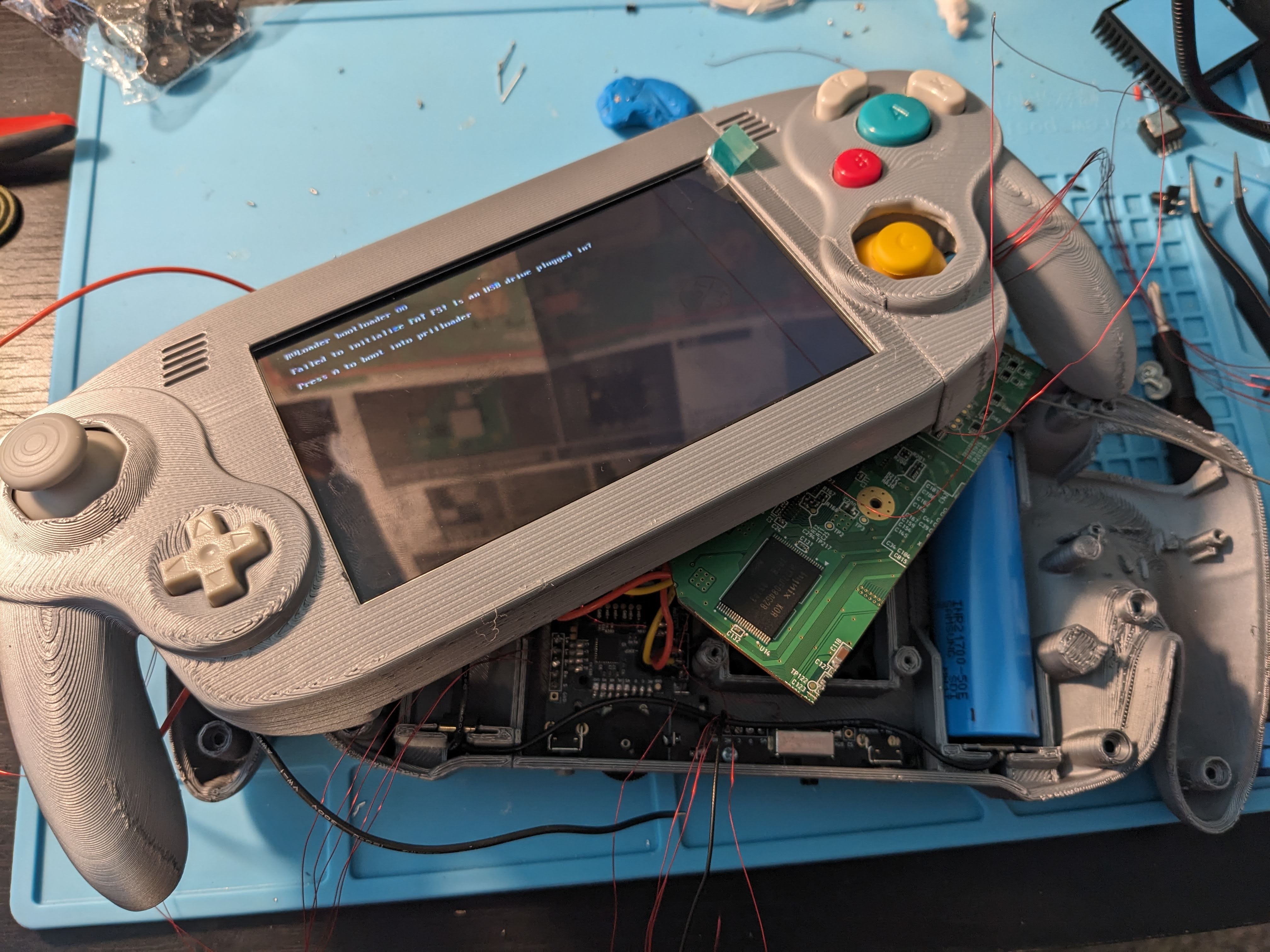
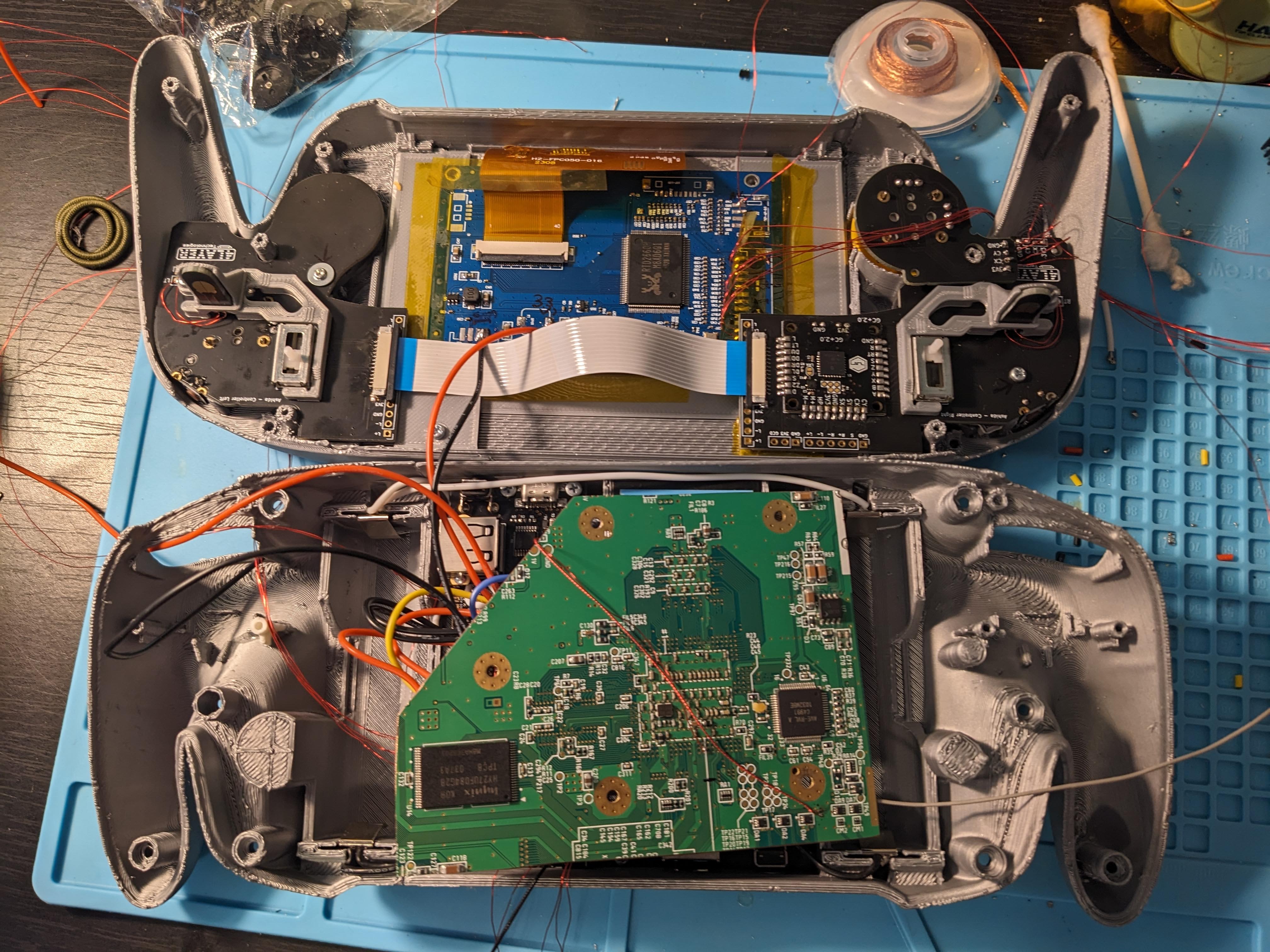
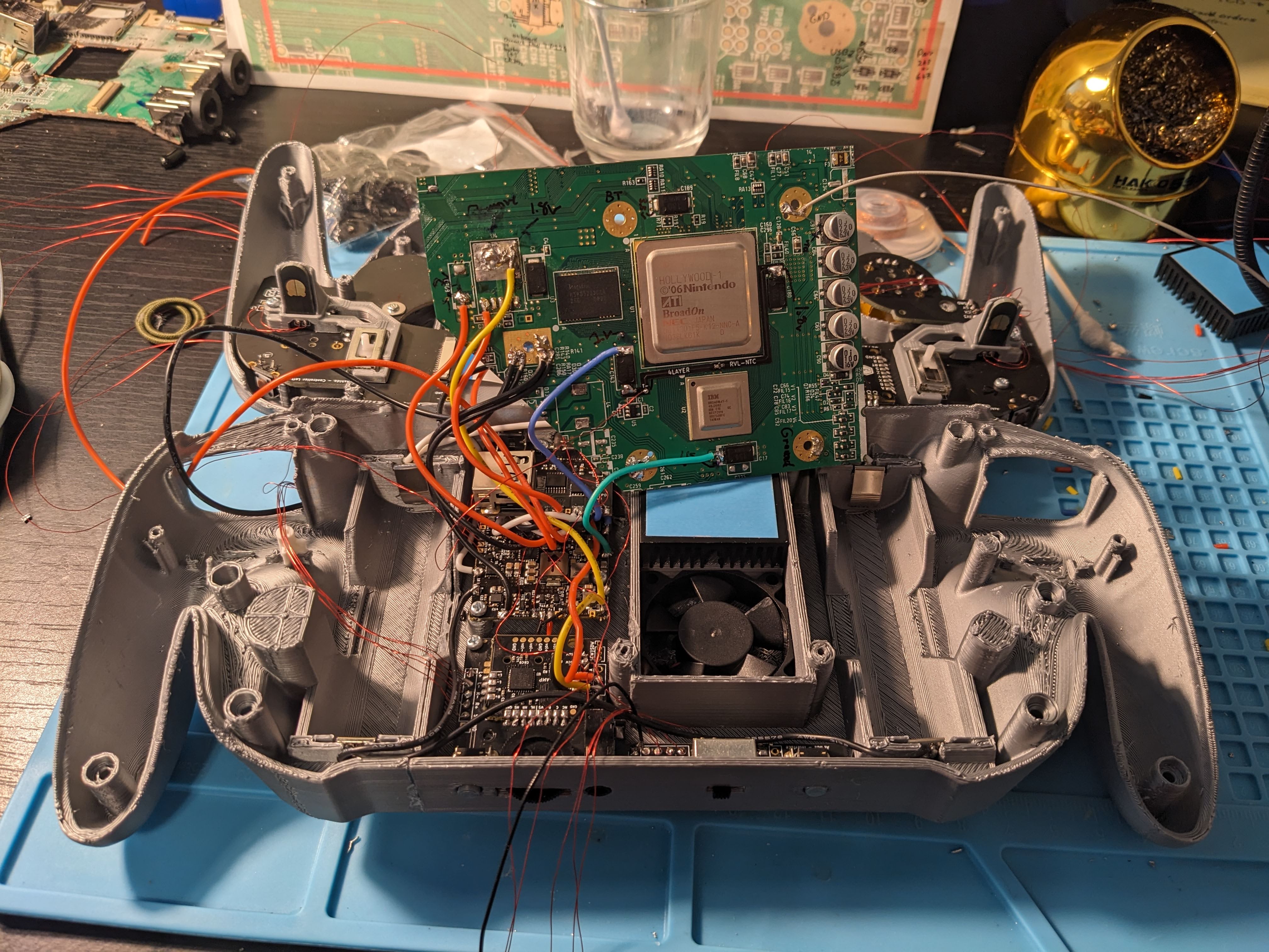
I am building my first portable, Wesk's Ashida. When booting the system up I run into the "Failed to initialize FAT FS! Is an USB drive plugged in?" error. I could use some help getting past this.
Things I have tried:
1. Tightly twisting the data lines and making sure they are exactly the same length. I also shorted the wires to about as short as they will go.

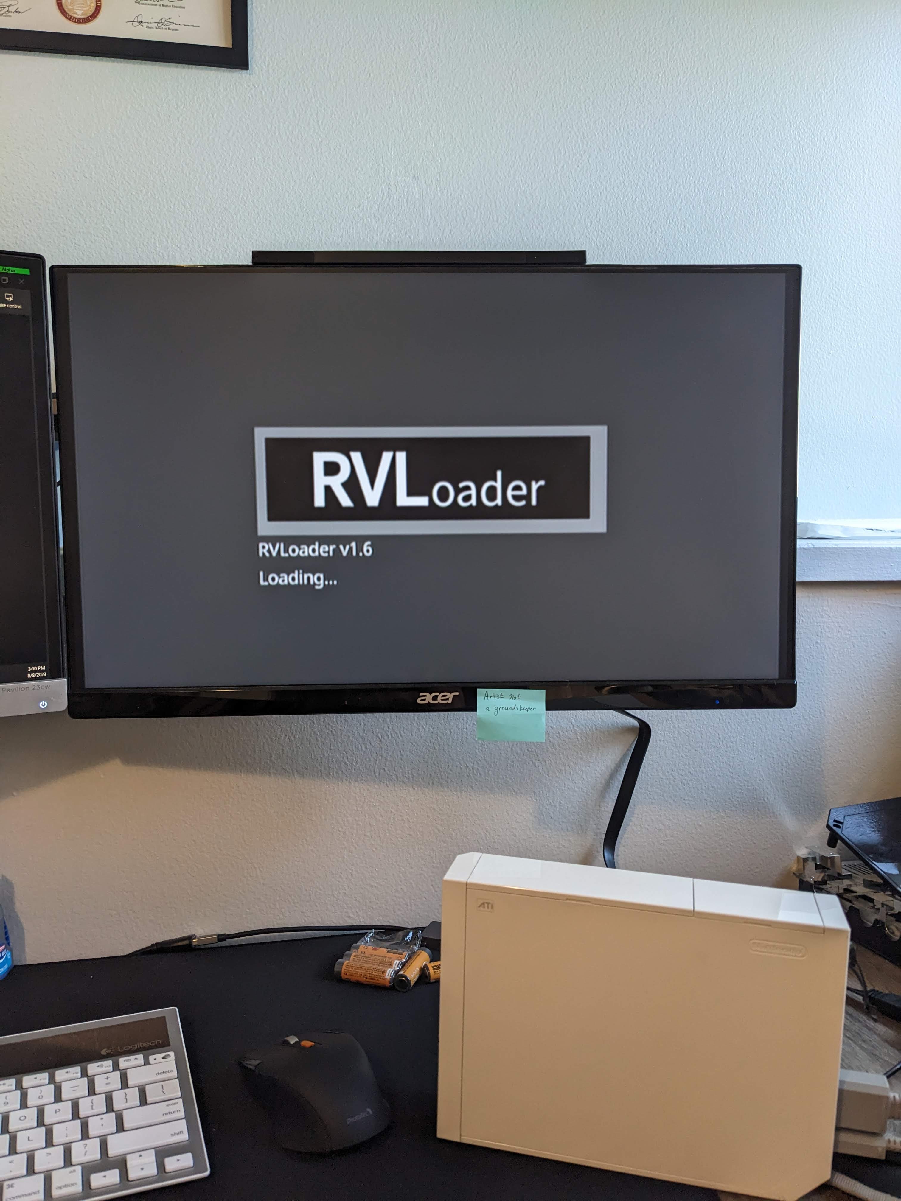
2. Plugging the USB drive into another Wii with RVLoader installed. Worked great on the other Wii, it booted without issue.

3. Power cycling...
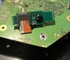
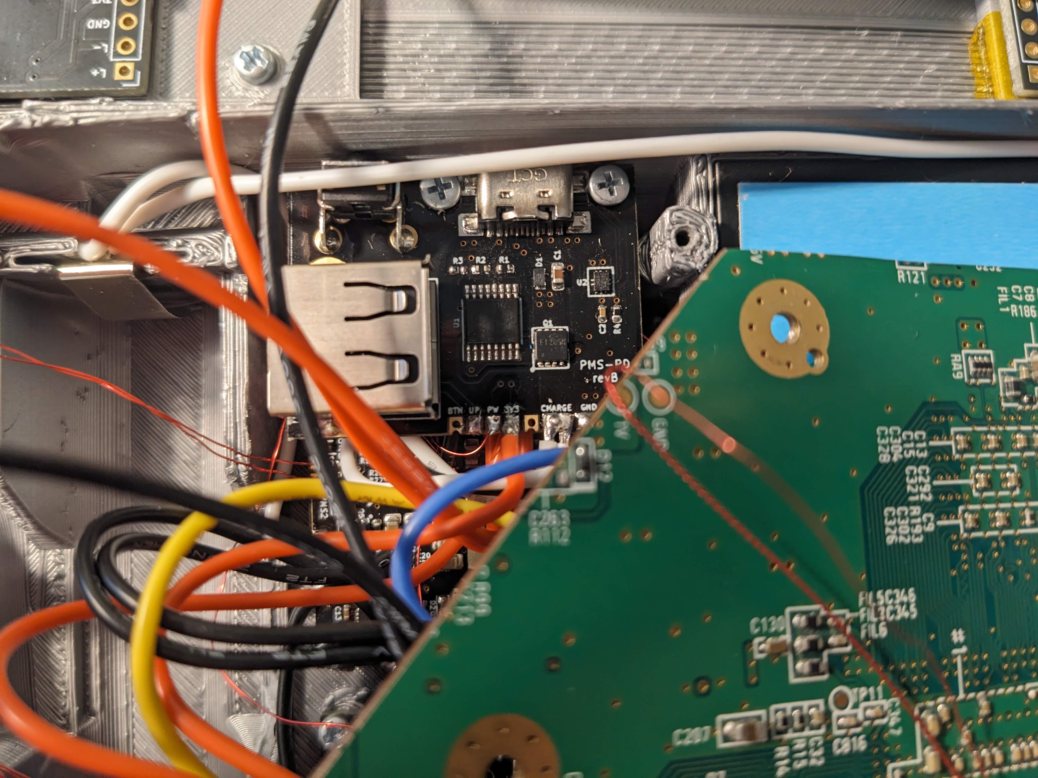
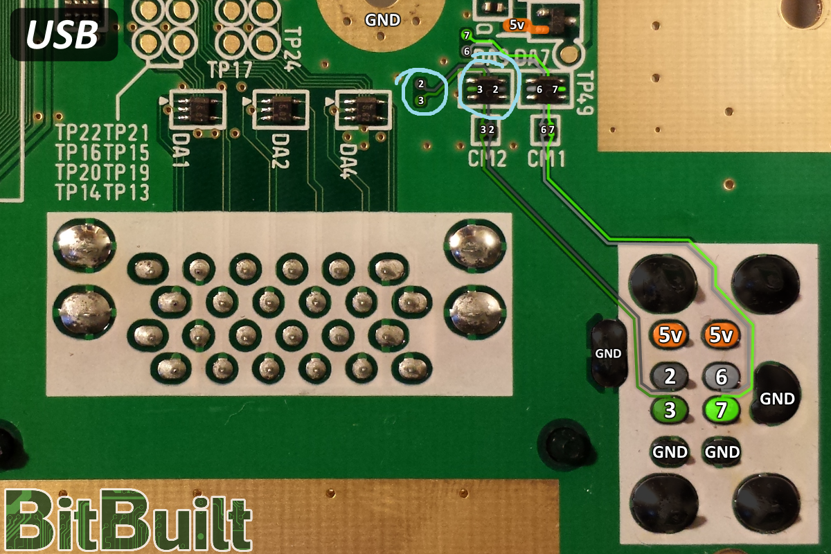
4. Checked the continuity between the PMS-PD D+ and Via 3 and the left side of the black component (I don't know the name, see image.)
5. Checked the continuity between the PMS-PD D- and Via 2 and the right side of the black component (I don't know the name, see image.)
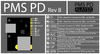
6. Checked the voltage of the "UP" via(?) on the PMS-PD 2, it was 5v. (I did wire "UP" to the PMS's "UP" with 34awg wire which might be too small.)
7. (UPDATE) I just tried connecting the PMS-PD 2's D+ and D- to Vias 6 and 7 from the image above (thinking there could be an issue with vias 2 and 3) I had the same issue.
8 (UPDATE) Is there a way to test the PMS-PD 2 to make sure the data lines are connected to the USB port correctly? I tried testing continuity between the D+ pad -> USB D+ port and the D- pad to the USB D- port and had high resistance. I assume this is due to the data line going though an IC on the board.
USB Drive:
This is the USB Drive I am using: SanDisk 128GB Ultra Fit USB 3.1
Which is vetted by GingerOfOz
So far I have:
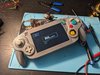
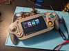
The PMS powering: the battery (only using one while troubleshooting,) MoBo, screen, PMS-PD 2, and Ashida audio board. NOT POWERING: the Ashida controller board (TODO.)
The MoBo is connected to:
-PMS via 3.3v, 1.8v, 1.15v, 1v, GND(*2), and the U10 line.
-The screen via Component (will switch to VGA later.)
-The PMS-PD 2 via the USB vias mentioned above in #4 and #5.
This is my first time using BitBuit (or any form for that matter.) Please don't eat me alive. ; )
More pictures:
I am building my first portable, Wesk's Ashida. When booting the system up I run into the "Failed to initialize FAT FS! Is an USB drive plugged in?" error. I could use some help getting past this.
Things I have tried:
1. Tightly twisting the data lines and making sure they are exactly the same length. I also shorted the wires to about as short as they will go.
2. Plugging the USB drive into another Wii with RVLoader installed. Worked great on the other Wii, it booted without issue.
3. Power cycling...
4. Checked the continuity between the PMS-PD D+ and Via 3 and the left side of the black component (I don't know the name, see image.)
5. Checked the continuity between the PMS-PD D- and Via 2 and the right side of the black component (I don't know the name, see image.)
6. Checked the voltage of the "UP" via(?) on the PMS-PD 2, it was 5v. (I did wire "UP" to the PMS's "UP" with 34awg wire which might be too small.)
7. (UPDATE) I just tried connecting the PMS-PD 2's D+ and D- to Vias 6 and 7 from the image above (thinking there could be an issue with vias 2 and 3) I had the same issue.
8 (UPDATE) Is there a way to test the PMS-PD 2 to make sure the data lines are connected to the USB port correctly? I tried testing continuity between the D+ pad -> USB D+ port and the D- pad to the USB D- port and had high resistance. I assume this is due to the data line going though an IC on the board.
USB Drive:
This is the USB Drive I am using: SanDisk 128GB Ultra Fit USB 3.1
Which is vetted by GingerOfOz
So far I have:
The PMS powering: the battery (only using one while troubleshooting,) MoBo, screen, PMS-PD 2, and Ashida audio board. NOT POWERING: the Ashida controller board (TODO.)
The MoBo is connected to:
-PMS via 3.3v, 1.8v, 1.15v, 1v, GND(*2), and the U10 line.
-The screen via Component (will switch to VGA later.)
-The PMS-PD 2 via the USB vias mentioned above in #4 and #5.
This is my first time using BitBuit (or any form for that matter.) Please don't eat me alive. ; )
More pictures:
Attachments
-
 1.4 MB Views: 40
 -
 870.8 KB Views: 43
Last edited: