
You are using an out of date browser. It may not display this or other websites correctly.
You should upgrade or use an alternative browser.
You should upgrade or use an alternative browser.
Worklog Pengy's first Wiip worklog
- Thread starter pengy
- Start date
pengy
.
- Joined
- Aug 22, 2016
- Messages
- 118
- Likes
- 47
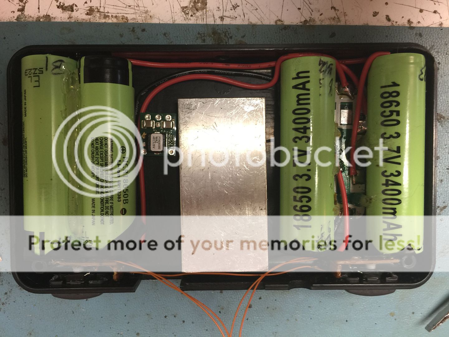
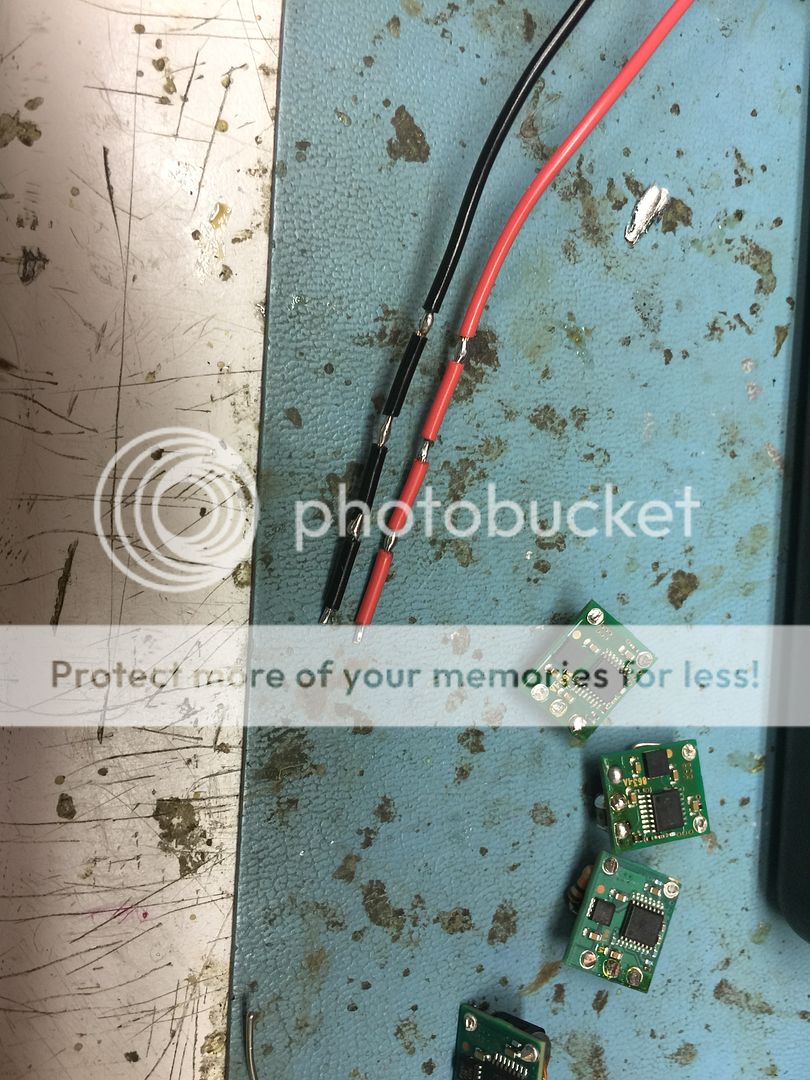
Thanks cheese. So I'm not getting anything so my gc controller must be improperly connected. I am pulling 3.3v and ground over by the LDO, and im using one of the pictured pins in the trimming guide for the controller hookup. As far as i could surmise, trimming it to where i did and wiring things directly to the chip on the controller was all I had to do. Now I'm starting to wonder if that's the case.... Does anyone have any ideas?
- Joined
- Feb 25, 2016
- Messages
- 1,465
- Likes
- 3,020
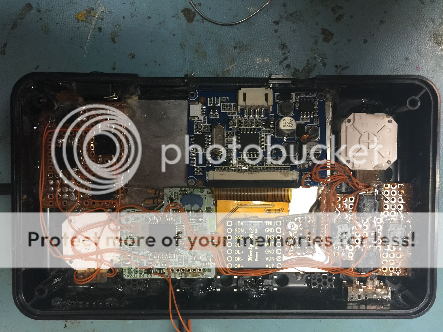
There is a small transistor at the top of the GC controller. Try soldering the data wire to the side of the transistor with only 1 pin. Do you know if the issue is that the buttons aren't working, or the controller just straight up is "not connected"?It's soldered to the pin called "data in" on the controller guide on this forum. I tried to copy the trim from your wiiboyv2 exactly.
- Joined
- Feb 25, 2016
- Messages
- 1,465
- Likes
- 3,020
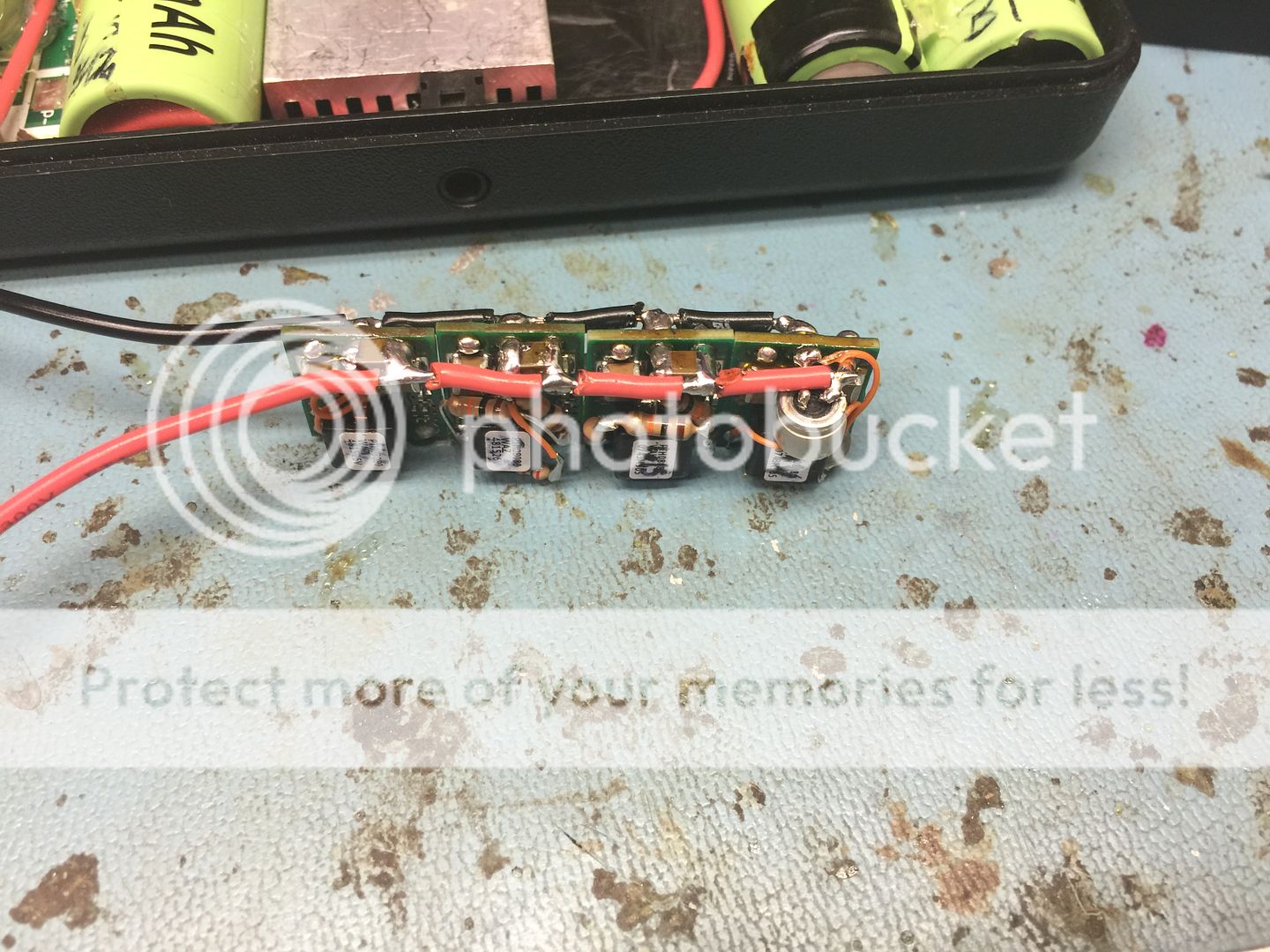
I haven't fully mapped out the data line circuit, but I've had your problem before and somewhere along the line it connects to that transistor and it seems to solve the issue.So the transistor leg as the data line seems to have solved the issue.... Do we have any idea why that solved the issue? Thanks gman lol.
- Joined
- Aug 2, 2016
- Messages
- 294
- Likes
- 146
do you plan on closing the unit with little screws on the side of the case? this is looking spectacular, Pengy
pengy
.
- Joined
- Aug 22, 2016
- Messages
- 118
- Likes
- 47
do you plan on closing the unit with little screws on the side of the case? this is looking spectacular, Pengy
Thanks bro. Yes, I will use the top two screwposts, and two small screws at the bottom.
")
Similar threads
- Replies
- 19
- Views
- 6K