NGCP
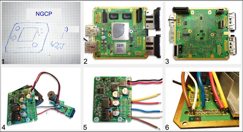
Many year ago when i was in school every week i watched Xplay tv show. Xplay make review on top best gamecube game. When it was i has only dandy. Then I think it best console in world. I very much wanted to get her for Christmas but..... And now after 10 year when i find this forum and learned about GC mod chip and how many peoples make portable console I decided to make a pocket version of the NGCPocket.
When I started I was nothing: cube, gamepad, memcard, display, buttons, triggers, mod mod chip etc. Almost all parts ordered from different countries, in my country gc - rarity.
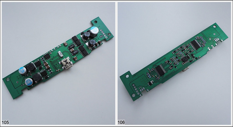
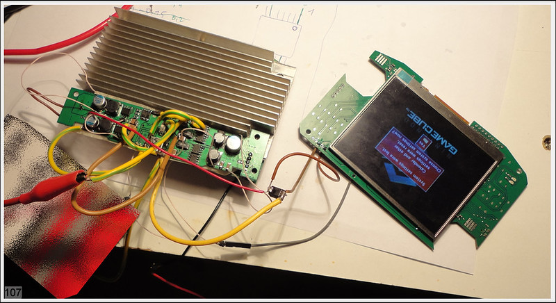
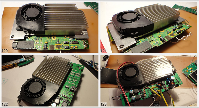
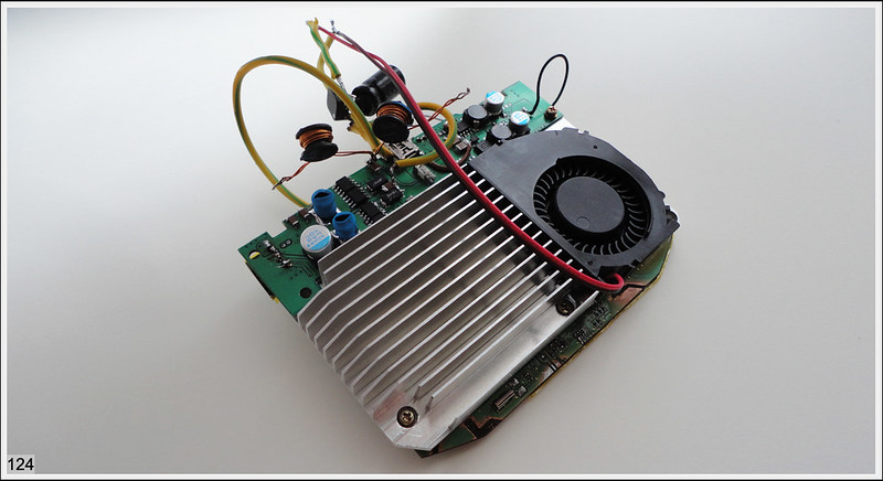
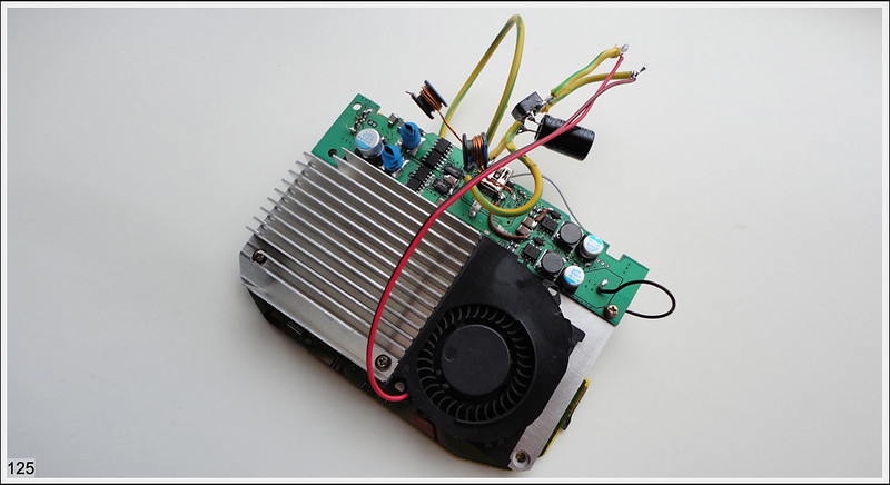
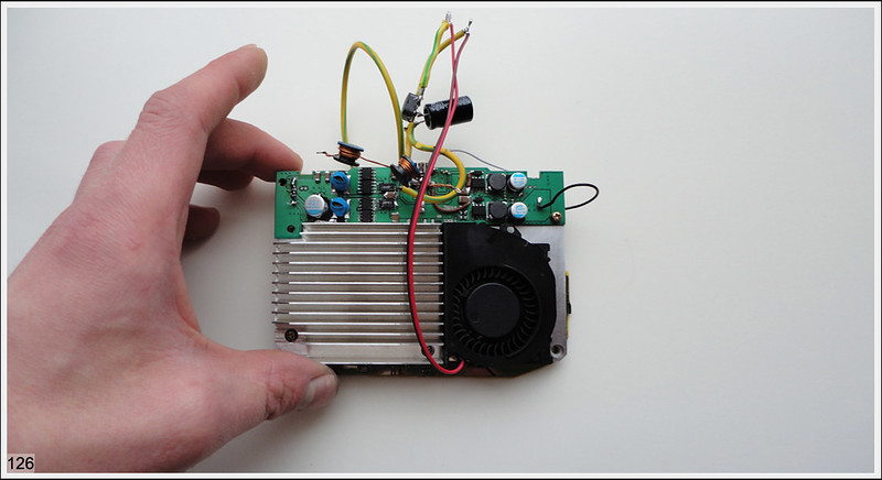
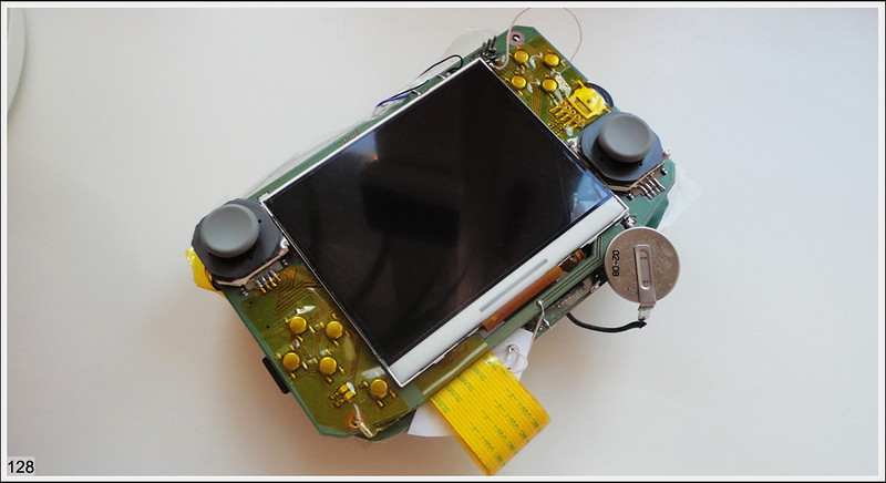
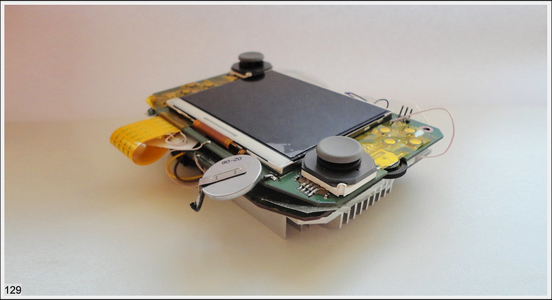
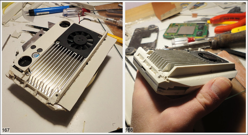
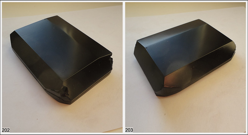
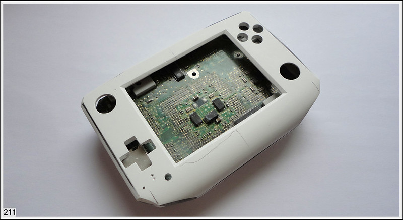
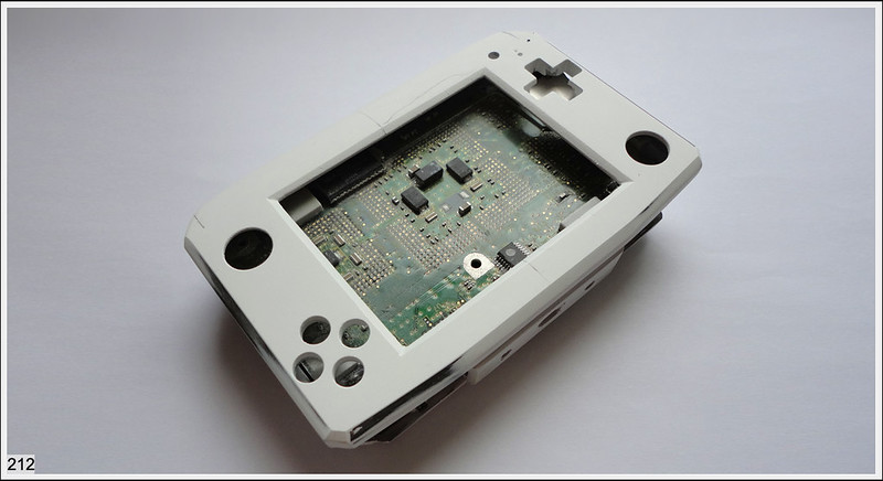
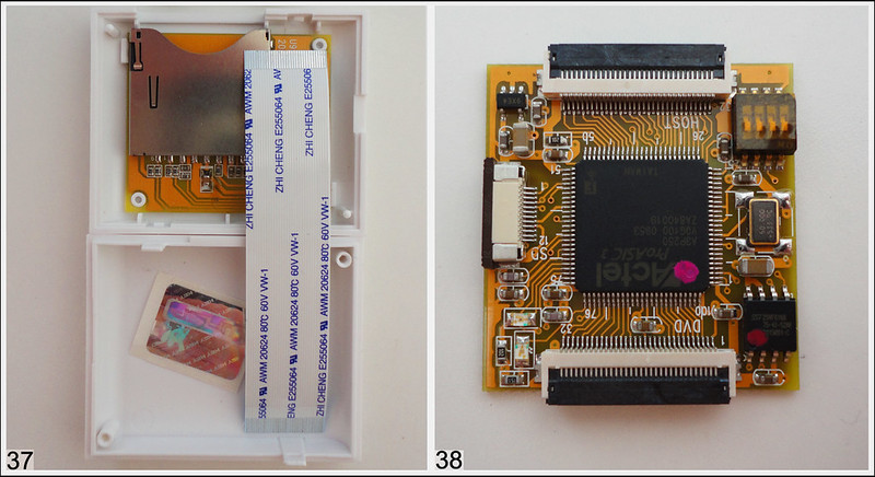
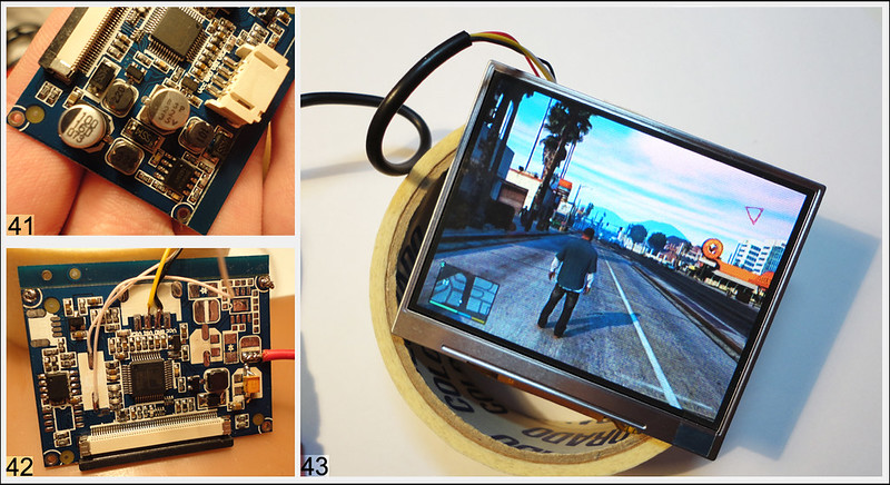
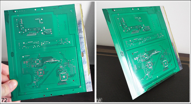
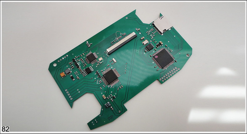
Today I received my console and already break it. Dimensions motherboard 11,9x12,6Sm (Pic 2,3) I ordered a small 3.5-inch display, controller, tact switches and another parts. Having dealt with the power supply. It is possible to remove the 12v supply line, and replace them on the five volts. We save 1 wire and plenty of space. The power board will be beyond the console.
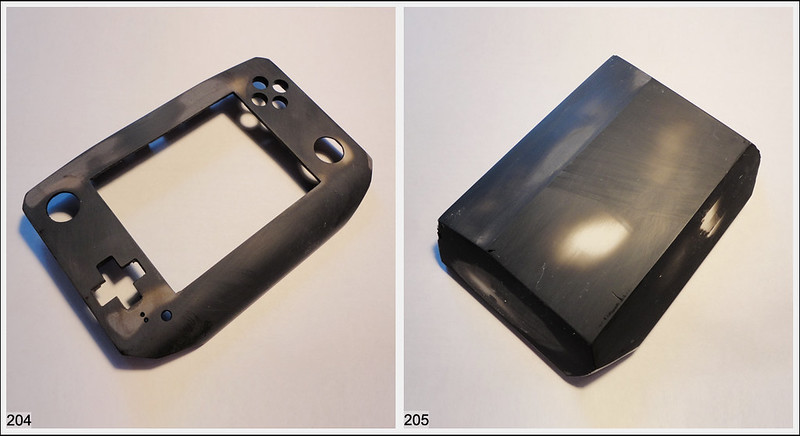
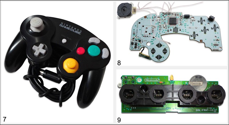
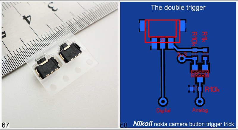
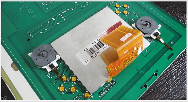
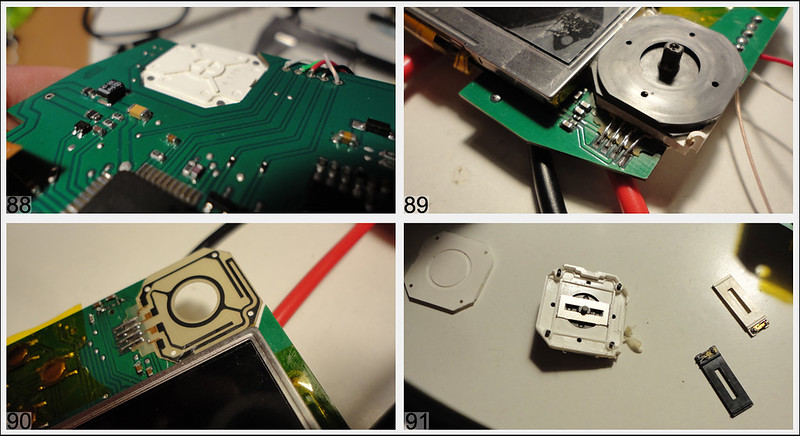
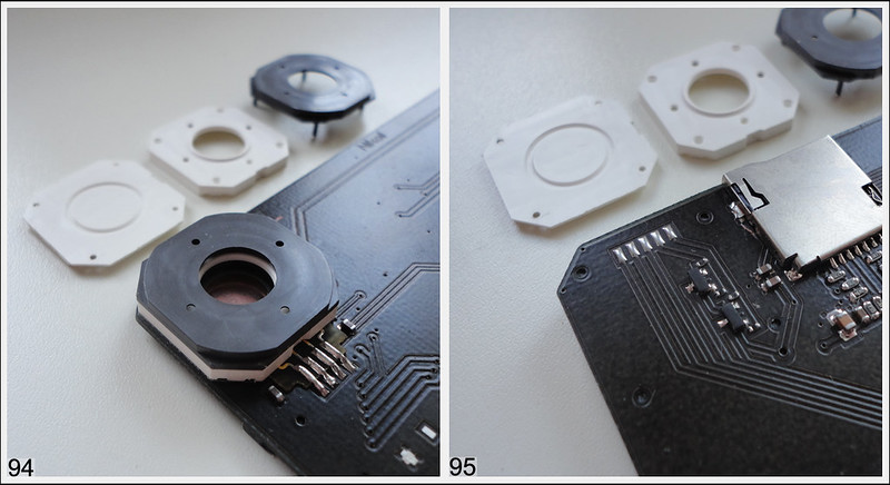
Disassembled joystick (pic 7-8) and controller board (pic 9). I will be use 3ds stick. Plastic case, controller board - no more needed.
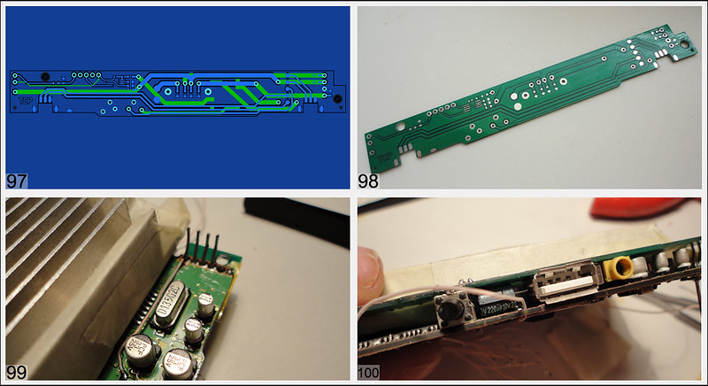
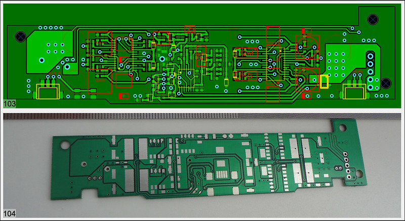
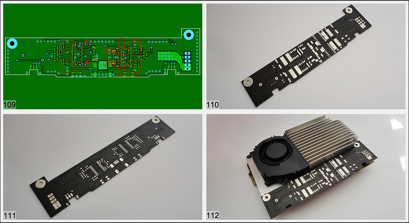
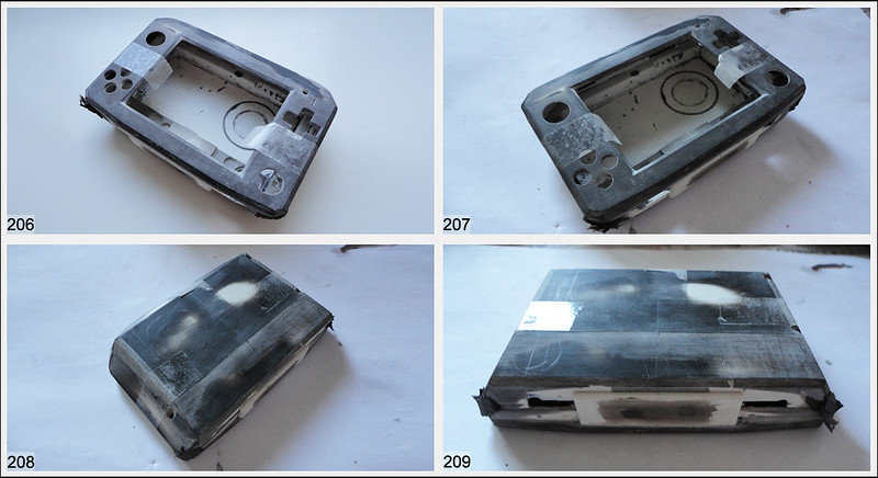
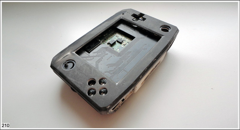
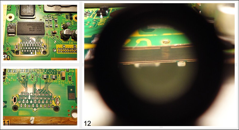
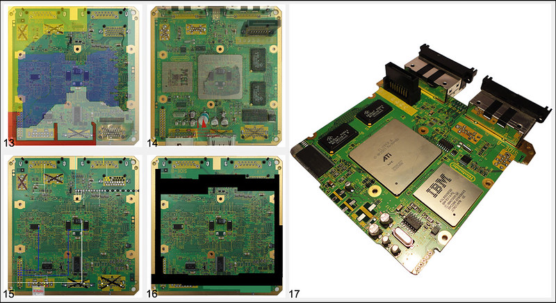
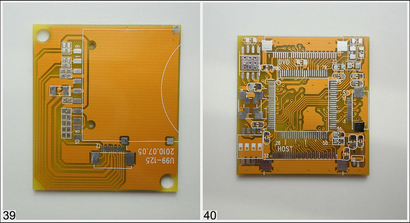
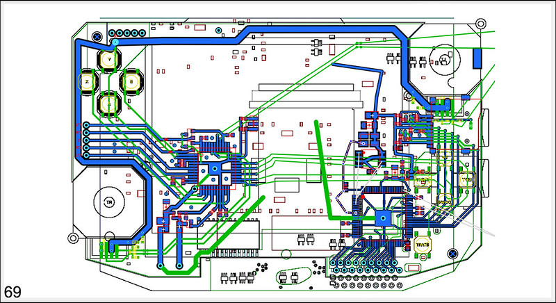
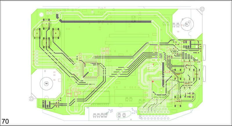
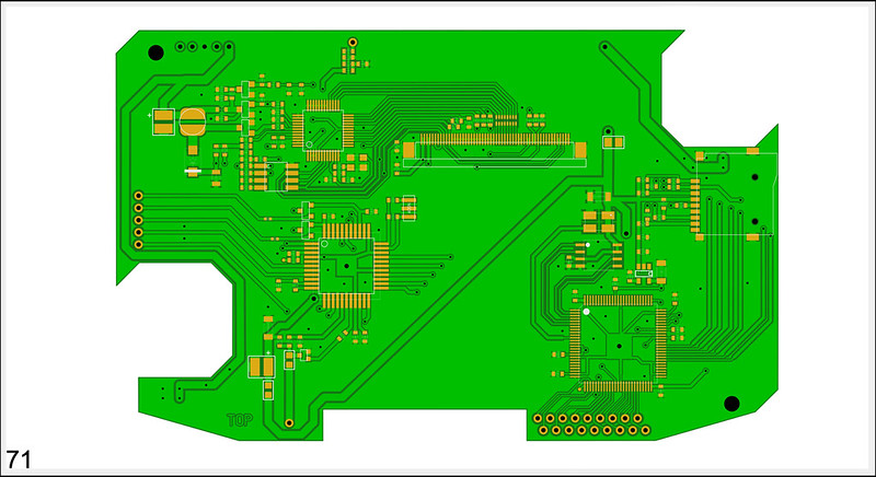
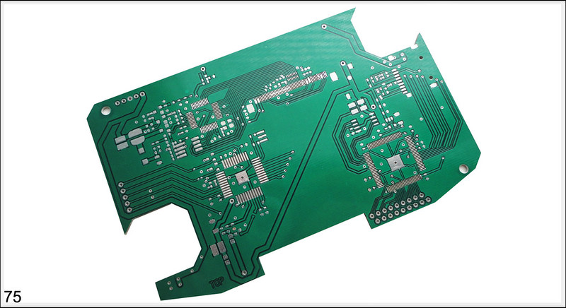
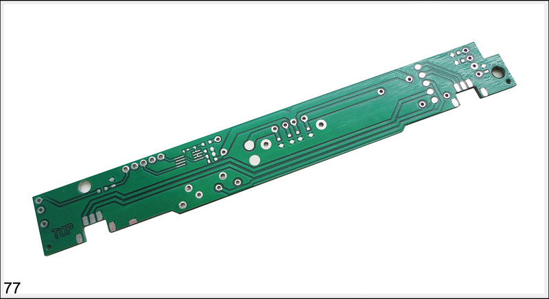
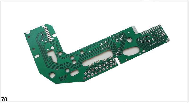
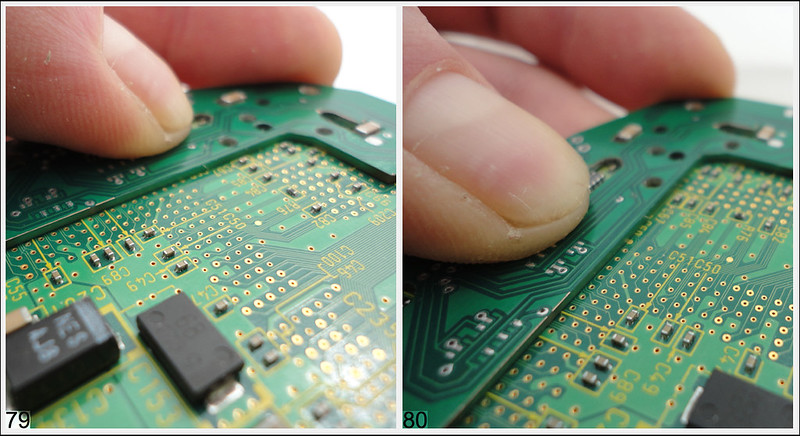
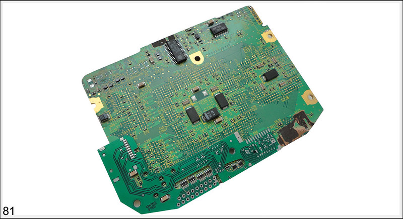
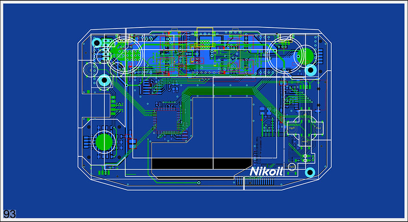
Started working with the motherboard. No schemes and datasheet - too bad! Pcb has 4 layers and thickness - 2mm. Need make power line map and delete many components . Photos 10-11 Handy X-rays.)
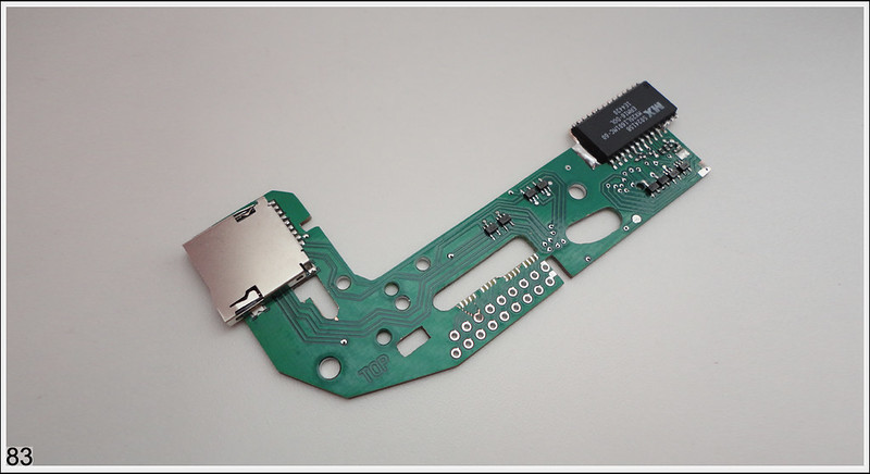
On (pic.13) remapping supply lines, transparent overlay for making the necessary circuits (pic.14). (Pic.15) pinout picture. Pic.16 is a cutting board line. The last photo of my motherboard after partial cutting. There were problems with the board after cutting, 5v line was in short circuit , and all because I was too lazy and not accurate

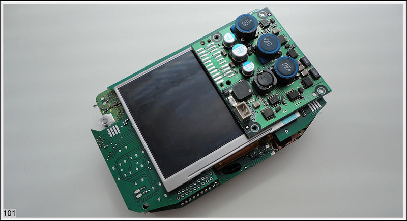
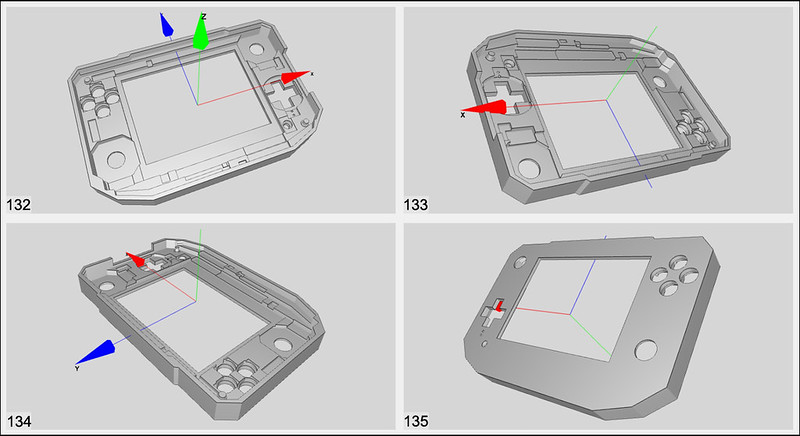
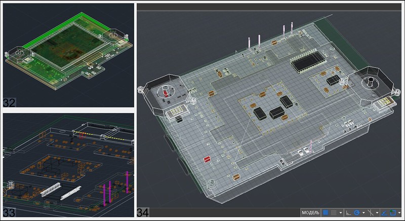
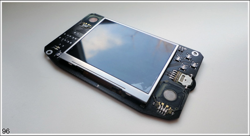
In AutoCAD I started modeling accessories and components. Attach a photo 3ds joystick (Pic 19), memory card, display, motherboard - 90% of the components.
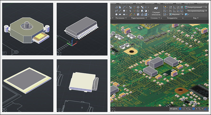
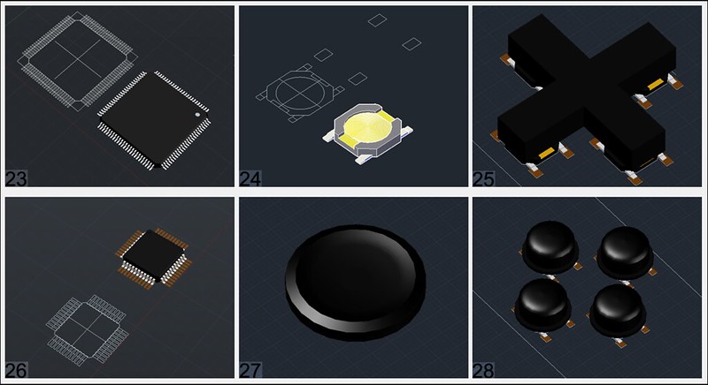
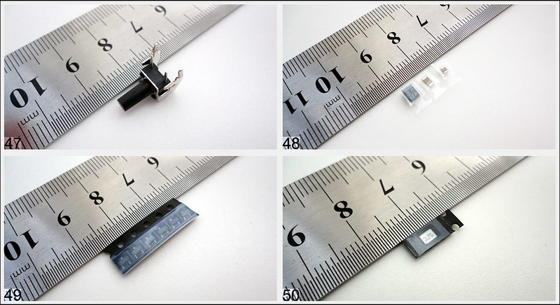
Few details: joysticks cpu, many buttons, wasp key cpu
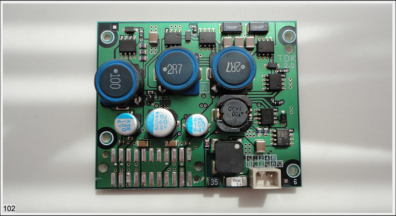
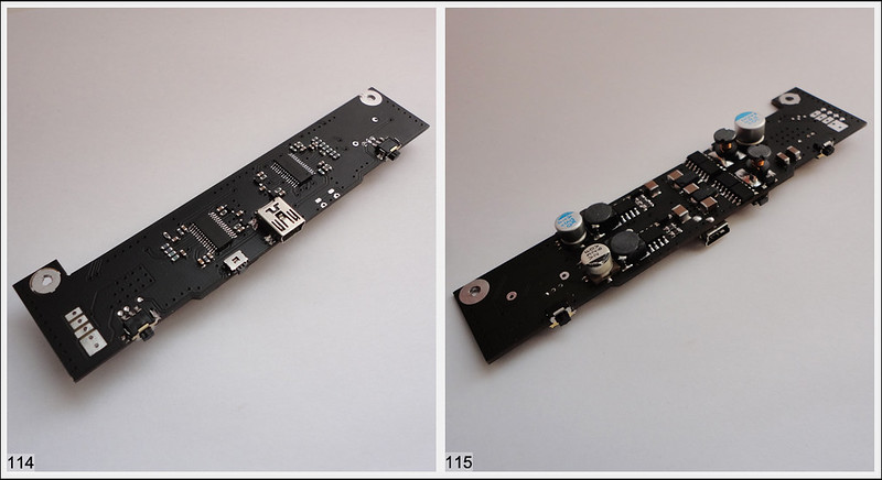
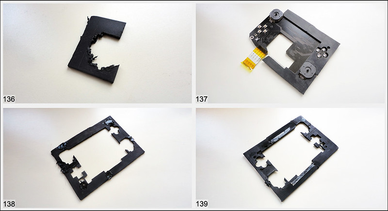
(pic30) main board prototype - v1
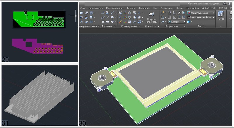
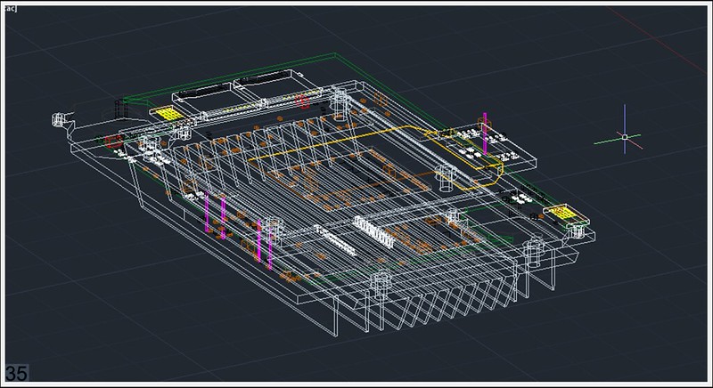
Continued. Expected thickness between the motherboard and prototype board - 3mm)
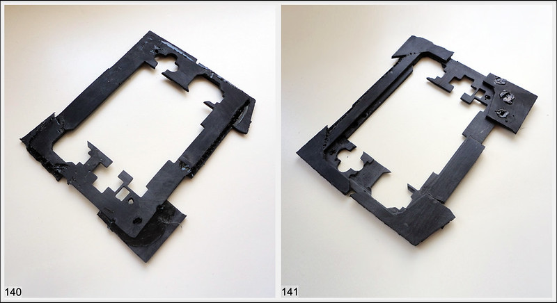
all together v3
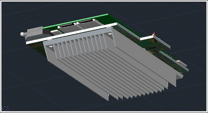
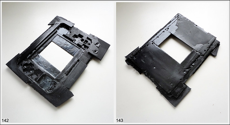
And v24 model
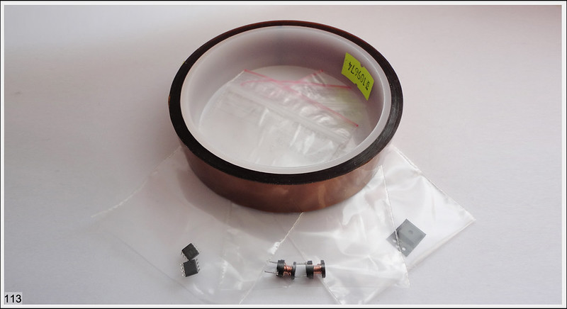
 And i forgot put in this pcb amp )


")