Question Wiring RVL-PMS 2 to LMAO V2 trim

Joined
Apr 8, 2020
Messages
98
Likes
6
Sorry if this has been asked before, but most of the guides out there show how to connect an RVL-PMS 2 to an OMGWTF trim or a LMAO V1 trim. Can anyone give me resources or guides on how to wire pins and stuff from an RVL-PMS 2 to an LMAO V2 trim?
Also, if anyone can give me resources on how to wire composite/AV video to wii? All I can find is VGA.
 

Shank

Moderator
Staff member
.
.
Joined
Jan 31, 2016
Messages
1,288
Likes
2,727
Portables
6
Joined
Apr 8, 2020
Messages
98
Likes
6
Everything you just asked for is in the OMGWTF Trimming Guide and the LMAO trim thread
The locations are mostly the same. The ones that are different are marked in ShockSlayer's documentation here: https://bitbuilt.net/forums/index.php?threads/lmaov2-and-nand-relocation-guide.1961/

As for composite video, it's outlined in the wii trim guide. Composite is not great, especially on LCDs, so it's strongly recommend to avoid it and go with vga if possible.
Composite is the only one I can find with my desired screen size. Also, it's suitable for the type of portable I'm making.
As for the guide you sent me, I don't quite understand it. :blush:
Can someone explain it to me in a way that I understand?

This is what I have of wiring the RVL-PMS to the Wii. All I have to do is wire the 1.8V and the 3.3V.
IMG_20230604_163944.jpg
IMG_20230604_163926.jpg

IMG_20230604_164043.jpg
 

Stitches

2 and a Half Dollarydoos
Staff member
.
.
Joined
Feb 5, 2017
Messages
3,853
Likes
3,026
Location
Banana Bender Land, Australia
Portables
6
Come on dude, this is getting frustrating now. You performed the 1.8v tantalum capacitor relocation, but don't know where you should connect 1.8v to? Connect it to the positive end of the capacitor that you relocated, this is basic stuff. Also, if you'd read the Trimming Guide properly, you'd have seen in the Voltage section that the tantalum capacitor directly above the Hollywood chip is one of the 2 major 3.3v locations. Also also, if you'd read the Trimming Guide properly you'd have seen in the Audio/Video section that C91 to the right of the Hollywood chip is a convenient solder point along the composite video line.

I must say though, nice trim. Good clean, neat edges.

Side note: Your solder joints are cold and cloudy, I'd increase your soldering iron temperature and get some no-clean tacky flux.

EDIT: I've amended the Trimming Guide to add the missing 1.8v locations to the voltage diagram. Might prevent further confusion
 
Last edited:

Shank

Moderator
Staff member
.
.
Joined
Jan 31, 2016
Messages
1,288
Likes
2,727
Portables
6
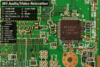
See the attached image from the guide. Pin 3 of the audio video encoder, in yellow, is composite. Run the composite video wire to any of those points.

As for 3.3v and 1.8v, there isn't really any specific ideal place to put them, on any trim for that matter. You don't have to run those or ground to the specific points in the 4 layer documentation: those are mostly a quick reference. All the points of the same voltage are connected through a big voltage plane on the center of the board. So as long as you are connecting it to part of that plane, you should be good. You can connect it where you see several vias, or to the relocated tantalum capacitors.

Also, your U10 line is not wired up, so your system will not boot. You will also need USB wired up as well.

Additionally, your wires look pretty thin. Make sure you are using at least 22awg for your power rails.

Regarding your soldering, I would advise touching it up. The joints look cold and not properly joined, which can cause issues down the line. Some of your leads are too long as well. You also have some scary stray strands going on, like one from the B+ that looks like it's about to short out your lithium battery to b-.

For soldering, you want both the wire and the pad you are soldering to to reach the melting temperature of the solder. Using flux (external flux, more than just the rosin core) makes life so much easier. Soldering without flux is like washing dishes without soap: possible, but why would you want to do things the hard way? If you are using lead free solder, switching to 63/37 leaded solder can make a huge difference. And make sure you are using a proper temperature controlled iron.

The hard part of the more advanced trims like these is not actually cutting the board. That's easy. The hard part is troubleshooting. You need to have a pretty good understanding of the board to work through the issues. You will find members of this forum guiding newer modders towards the easier and more documented trims because they want you to succeed. We point out issues bluntly because we want to help you dodge common pitfalls rather than watch you learn the hard way. I do believe you can perform this trim eventually, but I think you may be bitting off more than you can chew right now. I recommend performing the standard trim as outlined in the guide, then trimming the board smaller from there once you get that trim working. Perform step 1 before jumping to step 2.
 

Attachments

Top