
thedrew
.
- Joined
- Sep 27, 2016
- Messages
- 469
- Likes
- 1,050
A few months back, I was thinking of my childhood and impulsively purchased a Retroid Pocket 2 for nostalgia after seeing all of the good reviews. To be honest, I was disappointed and has been in a drawer ever since.
It's a bit of a learning process for me as I don't know much about the pi and I'm still learning as I'm going, but the goal is to build something better and more capable than the Retroid.
Here is a quick list of features I'd like to have:
- 3 to 4 hours battery life
- 800x480 4.3" IPS display (Now changed to a 5" IPS)
- 24bit direct drive from pi GPIO
- LCD brightness control
- Front firing speakers
- Removable micro sd card
- Usb slot for transferring roms to micro sd
- Arduino micro as gamepad with switch sticks
- Modded RVL-PMS as bms
I'll be using Vita action buttons and Dpad.
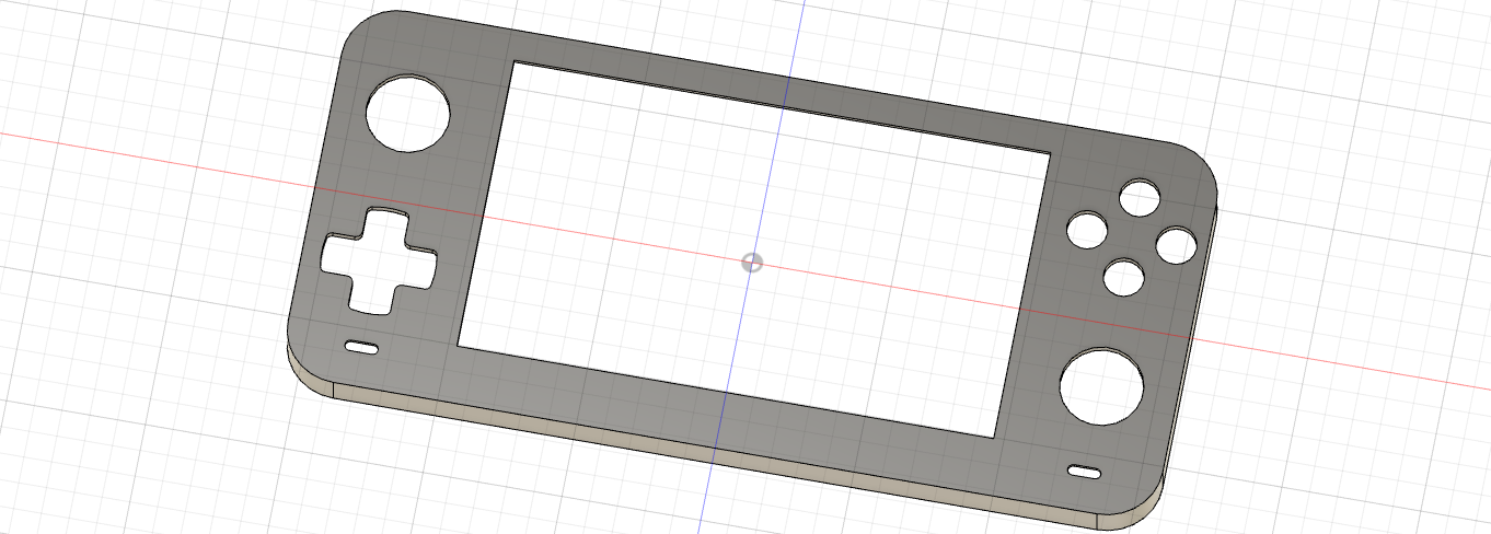
Current state of top half:
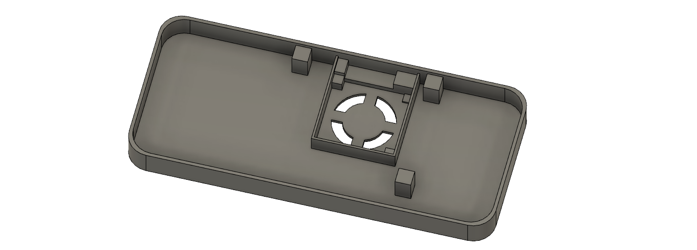
Current state of bottom half:
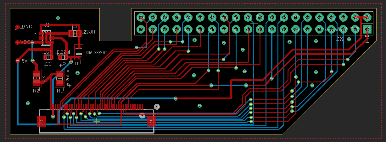
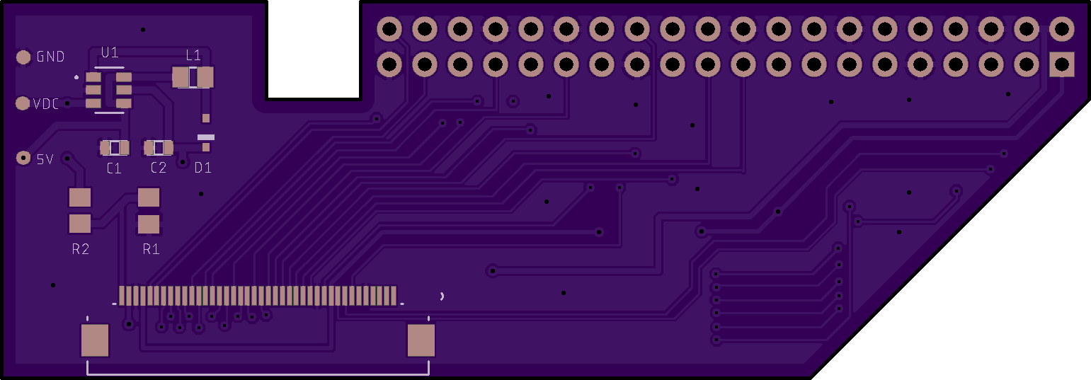
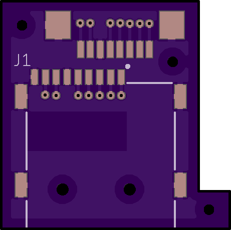
This is the custom direct drive circuit. This is a preview of a board but will be a flex. It is designed to be soldered on the bottom side of the pi, as when the pi board is screwed down in the case, the bottom side of the pi will be facing up toward the LCD. I'm using a PT4103 as the backlight driver and will have dimming control via a potentiometer thumbwheel.
I will be extending the micro sd slot from the pi to a simple custom board. An FFC connector will be soldered in alignment of the micro sd slot on the pi and connected to the board via an FFC cable.
There will be about 6 or so custom boards total for this handheld to make the assembly/internals much easier and cleaner. For the modified RVL-PMS, essentially I will be using the 5v reg but cutting off the top half of the board as I will not be using any of those regs and cannot fit the PMS in the case without trimming it. I'd rather not redesign the whole RVL as I already have extra blank boards laying around from a previous JLC order.
For the audio board, I will be using the HXJ8002 ic as it is class AB with super low distortion and practically doesn't distort at full volume. I've used this chip before and is my favorite audio amp to work with so far.
I still have the button boards, audio board, and peripheral board to finish and I'll be done with all of the custom boards .
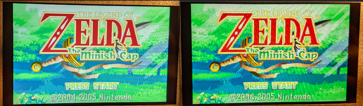
Lastly, I found a different 800x480 4.3" IPS LCD that is higher quality than the older 4.3" IPS screen we've all been using on the forums. Looks fantastic with a direct drive board I've been testing it with. It has better saturation, better contrast, and better viewing angles. Tried to capture it on camera but is way more apparent in person.
Left old, right new
Here's the link if anyone is interested. I did test this new LCD with an RTD2660 driver board and it doesn't work. Maybe a firmware or timing thing as the LCD has the same pinout.
https://www.aliexpress.com/item/1608099318.html?spm=a2g0s.9042311.0.0.adf14c4dFfW8ZZ
It's a bit of a learning process for me as I don't know much about the pi and I'm still learning as I'm going, but the goal is to build something better and more capable than the Retroid.
Here is a quick list of features I'd like to have:
- 3 to 4 hours battery life
- 800x480 4.3" IPS display (Now changed to a 5" IPS)
- 24bit direct drive from pi GPIO
- LCD brightness control
- Front firing speakers
- Removable micro sd card
- Usb slot for transferring roms to micro sd
- Arduino micro as gamepad with switch sticks
- Modded RVL-PMS as bms
I'll be using Vita action buttons and Dpad.
Current state of top half:
Current state of bottom half:
This is the custom direct drive circuit. This is a preview of a board but will be a flex. It is designed to be soldered on the bottom side of the pi, as when the pi board is screwed down in the case, the bottom side of the pi will be facing up toward the LCD. I'm using a PT4103 as the backlight driver and will have dimming control via a potentiometer thumbwheel.
I will be extending the micro sd slot from the pi to a simple custom board. An FFC connector will be soldered in alignment of the micro sd slot on the pi and connected to the board via an FFC cable.
There will be about 6 or so custom boards total for this handheld to make the assembly/internals much easier and cleaner. For the modified RVL-PMS, essentially I will be using the 5v reg but cutting off the top half of the board as I will not be using any of those regs and cannot fit the PMS in the case without trimming it. I'd rather not redesign the whole RVL as I already have extra blank boards laying around from a previous JLC order.
For the audio board, I will be using the HXJ8002 ic as it is class AB with super low distortion and practically doesn't distort at full volume. I've used this chip before and is my favorite audio amp to work with so far.
I still have the button boards, audio board, and peripheral board to finish and I'll be done with all of the custom boards .
Lastly, I found a different 800x480 4.3" IPS LCD that is higher quality than the older 4.3" IPS screen we've all been using on the forums. Looks fantastic with a direct drive board I've been testing it with. It has better saturation, better contrast, and better viewing angles. Tried to capture it on camera but is way more apparent in person.
Left old, right new
Here's the link if anyone is interested. I did test this new LCD with an RTD2660 driver board and it doesn't work. Maybe a firmware or timing thing as the LCD has the same pinout.
https://www.aliexpress.com/item/1608099318.html?spm=a2g0s.9042311.0.0.adf14c4dFfW8ZZ
Last edited: