Worklog CrazyGadget's First N64 Portable - NSight64

CrazyGadget

Crazy Helpful, CrazyGadget
.
Joined
Jun 6, 2020
Messages
611
Likes
879
Location
Downing's Closet
Portables
???
I've been doing Wii portables for quite some time now, and I've been starting to feel the monotony of the builds crushing my soul. I've been wanting to branch out into other consoles for quite some time now, but so many other projects have taken priority.... until now! This first post spans over the course of a couple days, leading up to a few hours ago...

DAY ONE

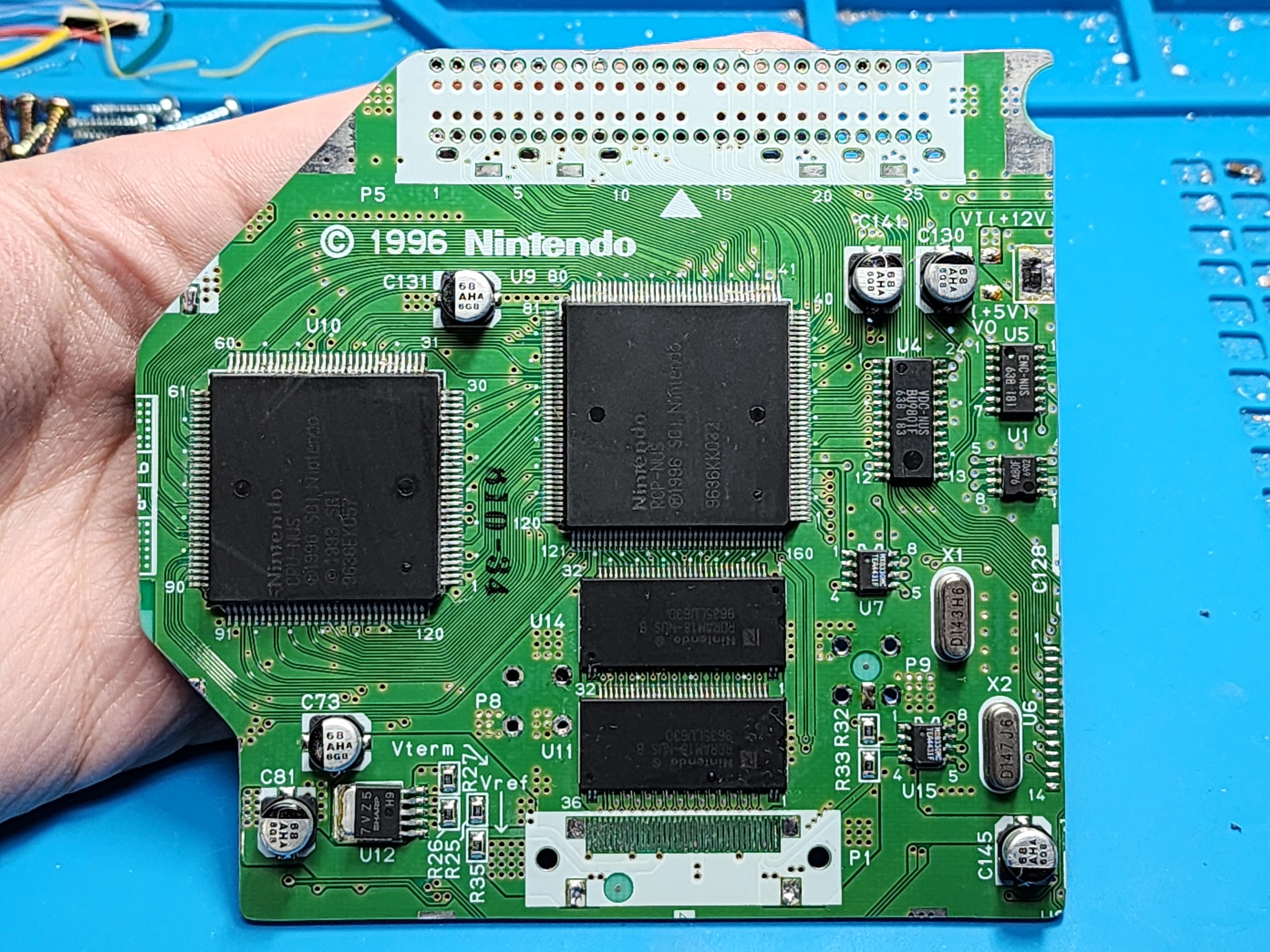
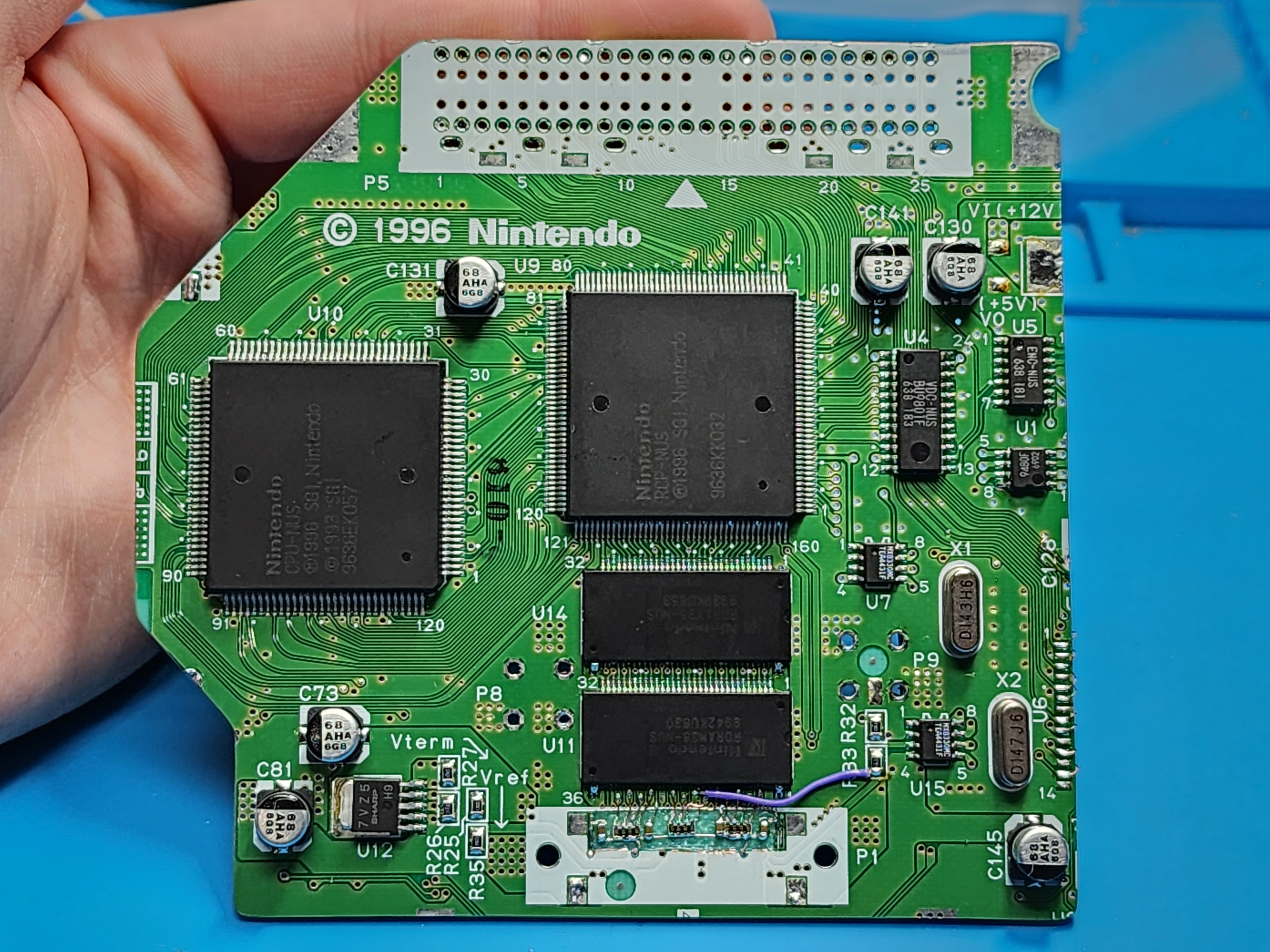
In between commissions, I've started to go down the N64 rabbit hole - reading through the advanced trimming guide and getting to understand all of the relocations and critical points on the N64. I've read through many worklogs (especially @SparkleBear's First N64p thread) and got super hyped up to try something myself. I bought a bunch of N64s with expansion paks, and one night I just went for it and did an advanced trim:

20230815_200333.jpg
20230815_200342.jpg


DAY TWO

In my portable-to-be, I wanted to swap the RAM for two 4mb chips as many have done. I also wanted to try my hand at the "Akira method" for RAM termination. In my craving to have a trimmed N64 in my hands, I failed to use my head and do these relocations before trimming. By not validating either of these relocations prior to trimming, I was potentially setting myself up for a big headache down the road if something didn't work correctly.

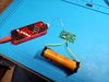
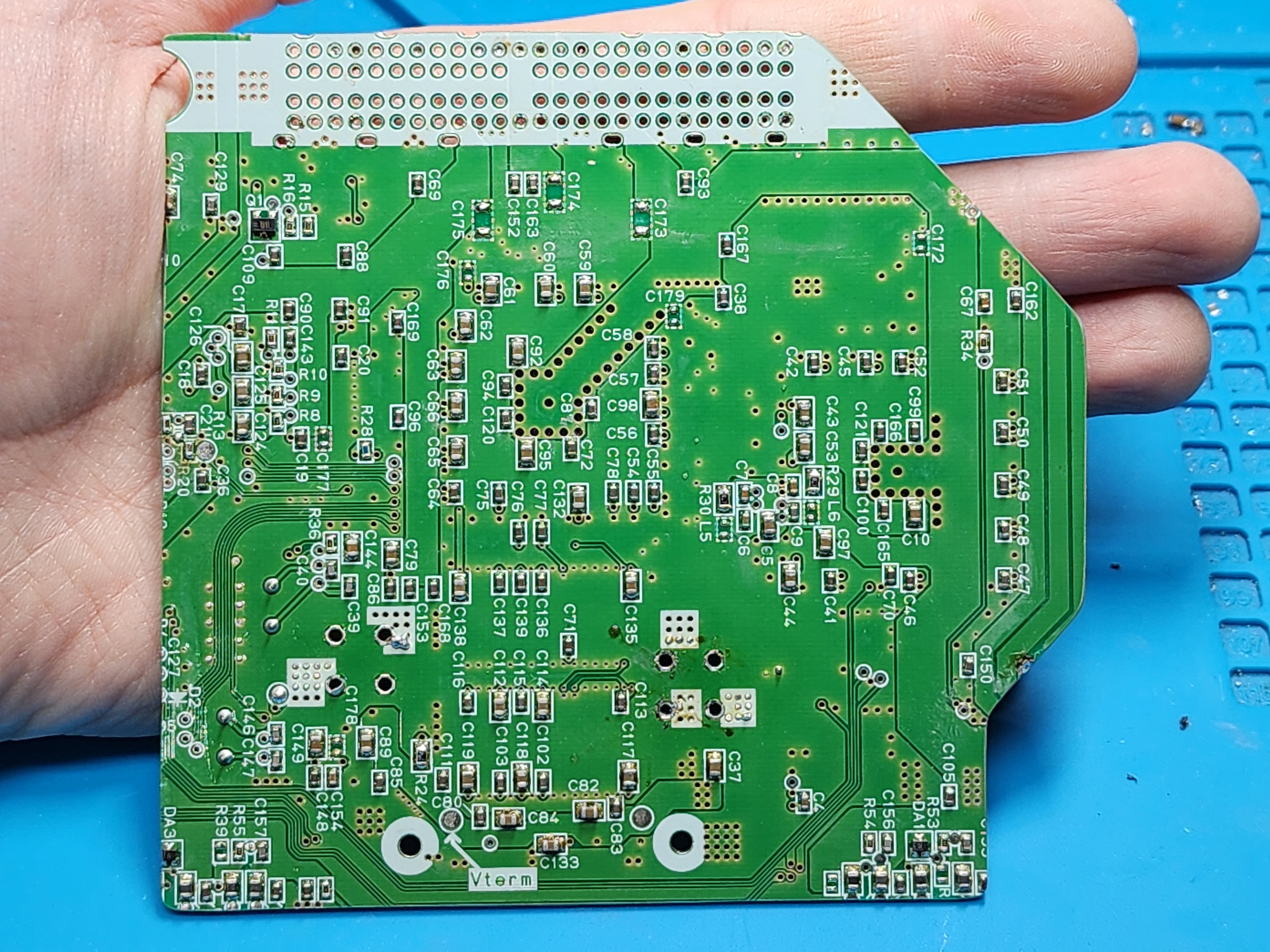
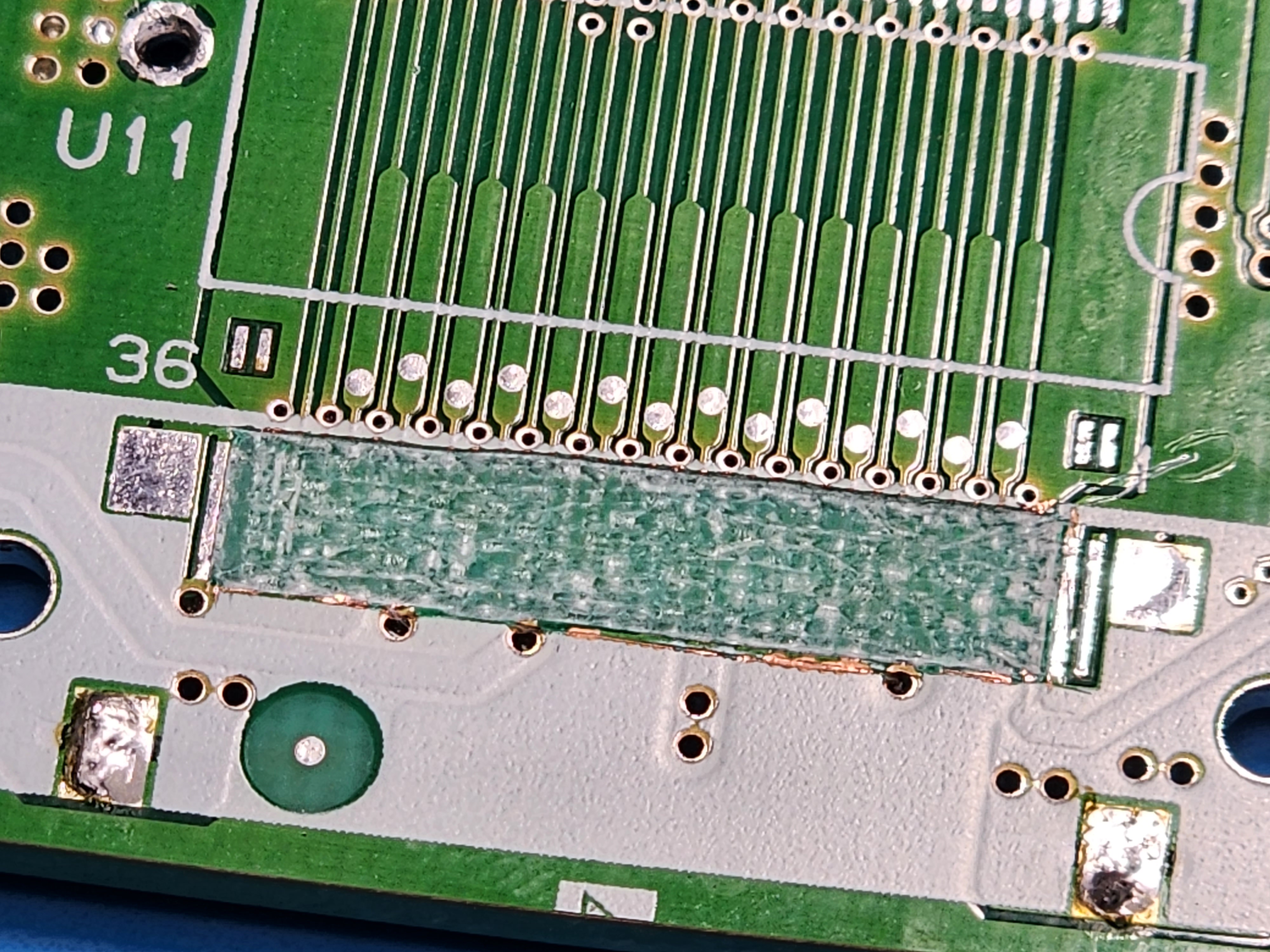
All that being said and understood, I got to work yesterday to start the relocation process. I have to start by thanking @YveltalGriffin for answering my many questions throughout the Akira method process. Equipped with a good understanding of what I need to do, I pulled the 2mb RAM chips from the board and cut out the RAM termination pins to expose the bare FR4:

20230908_150704.jpg


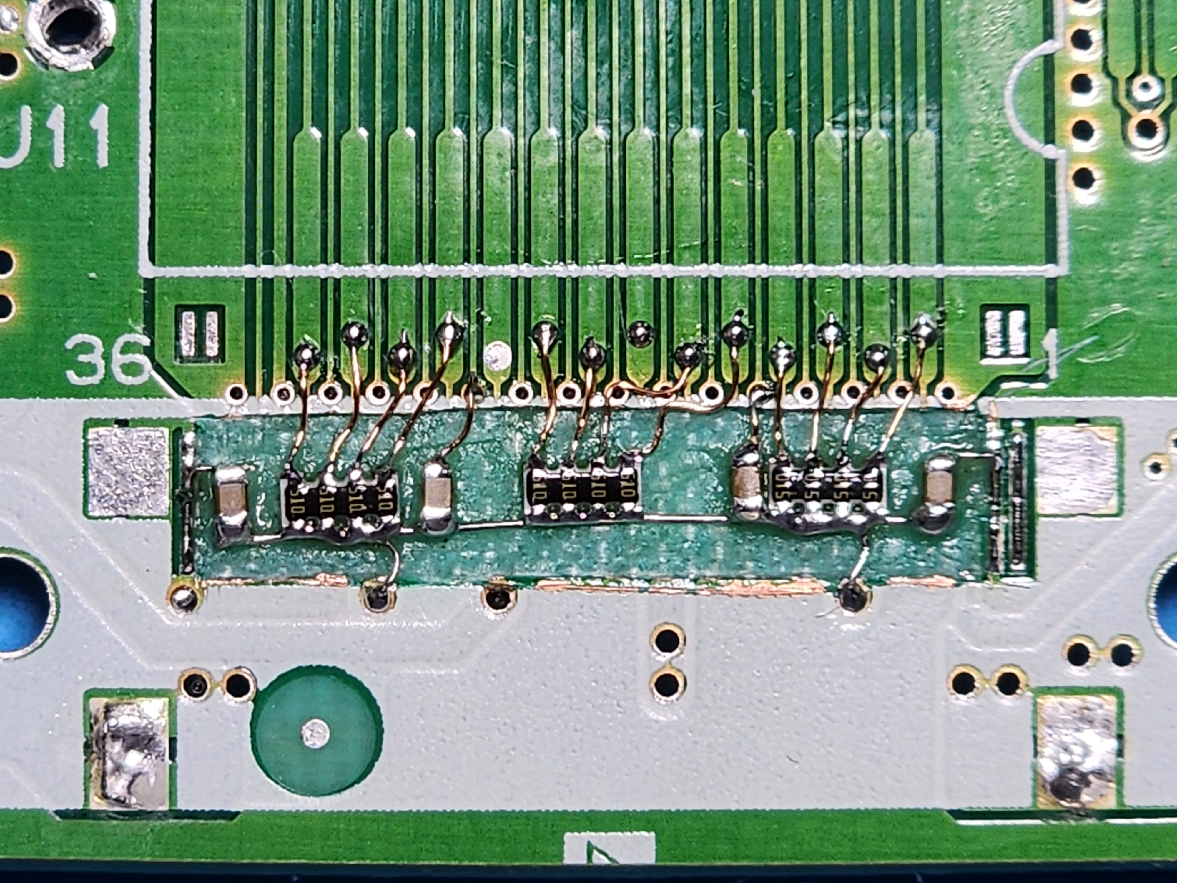
From there, I just followed the pictures Akira posted, and after about an hour and a half or so later, it was done!

20230908_165345.jpg


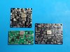
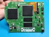
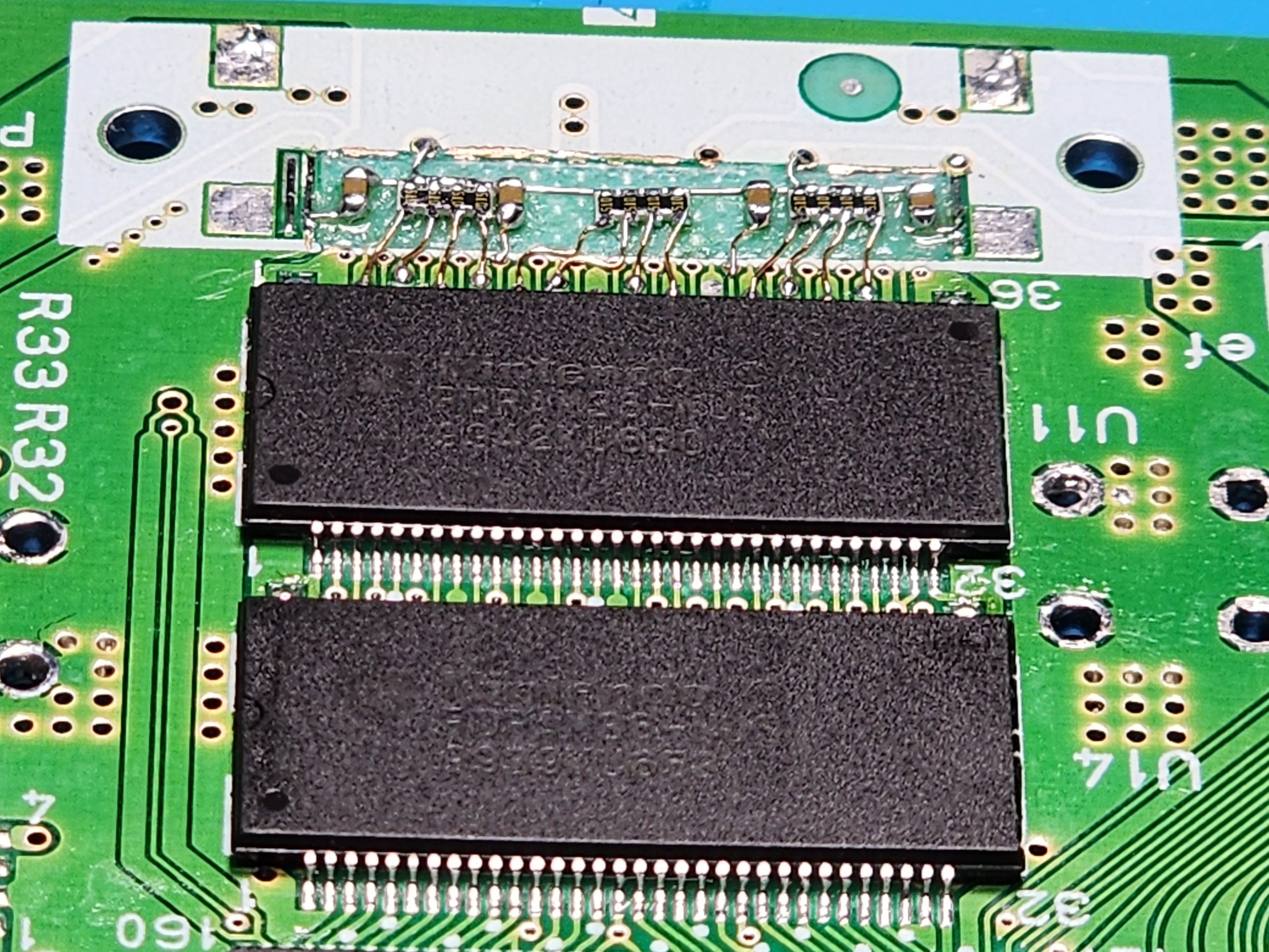
Yveltal was right: it's really not as scary as it's made out to be. After checking all my connections with my DMM to make sure all the pins had the right resistances to ground and none of them were shorted together, I added the 4mb RAM chips from two expansion paks:

20230908_172350.jpg


DAY THREE (current day)

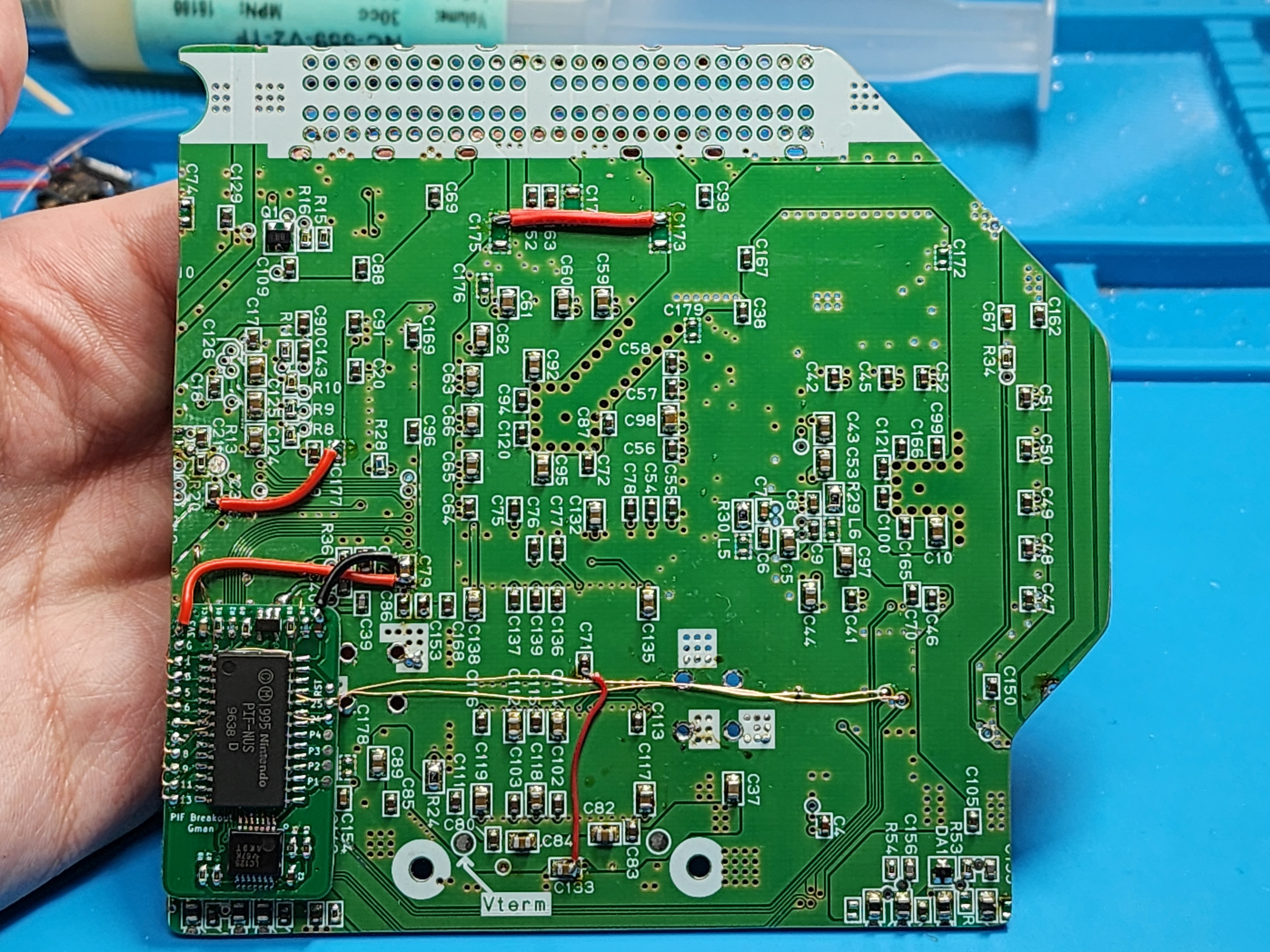
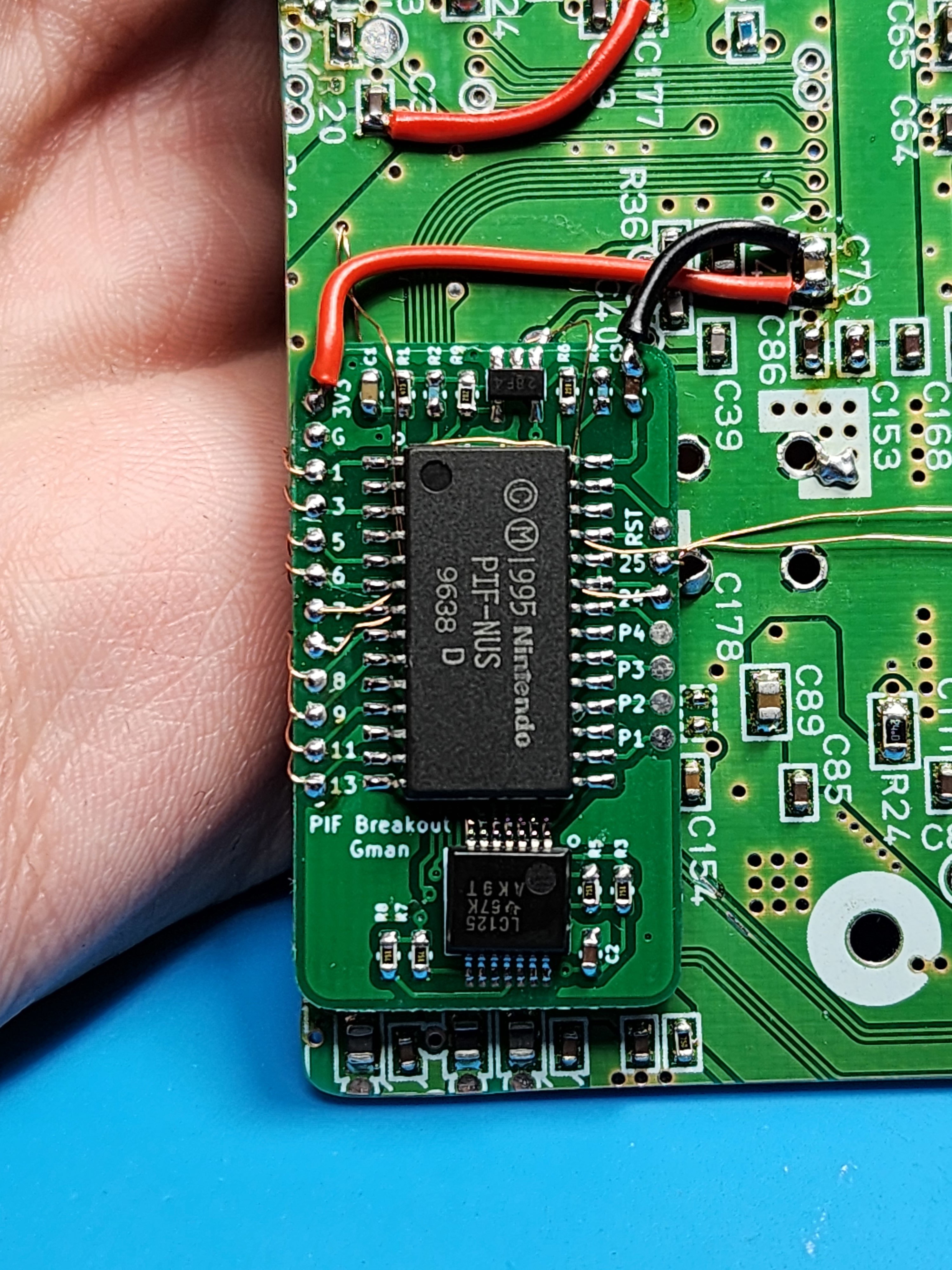
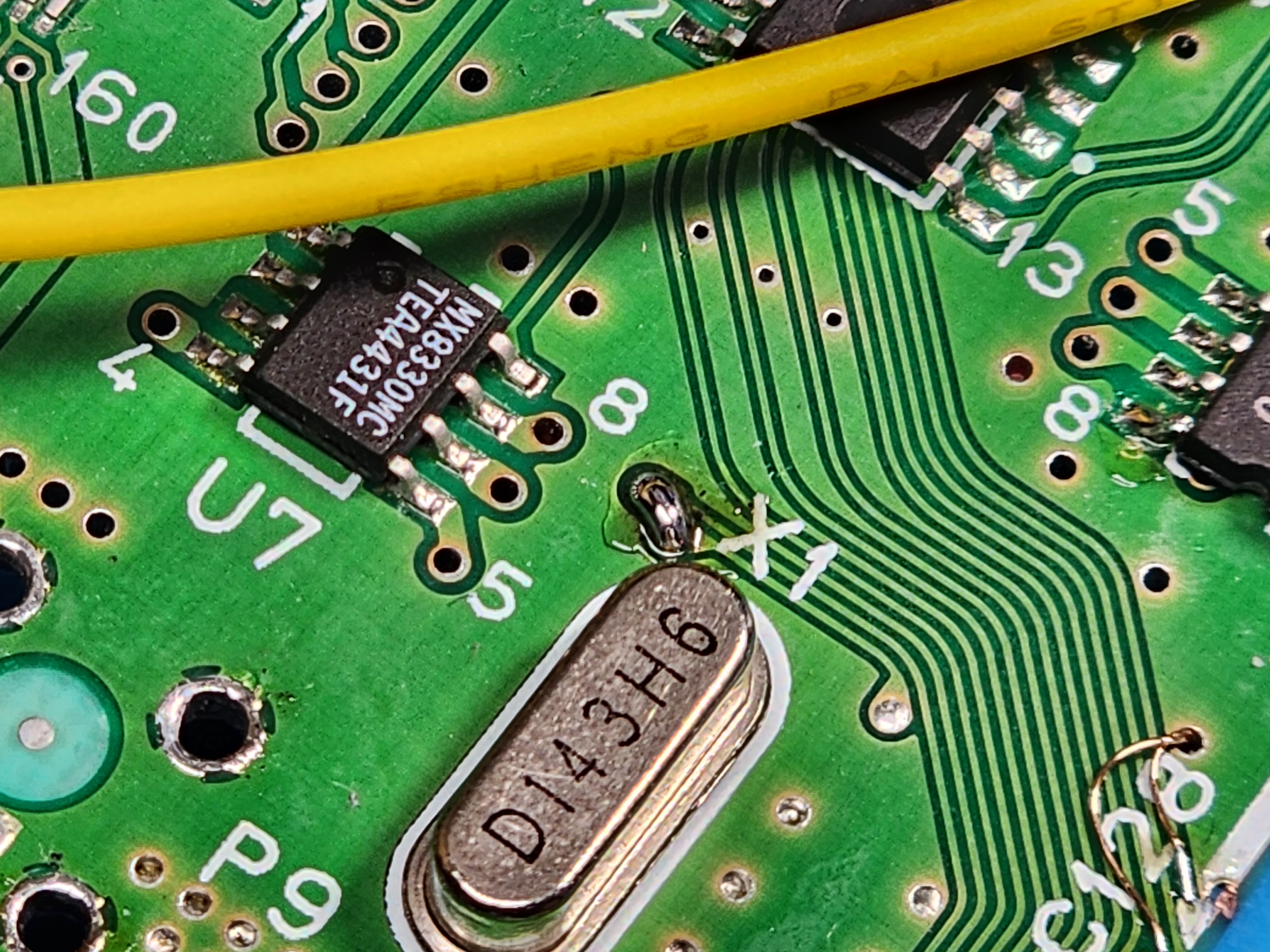
I did a lot of studying for the PIF relocation and used my DMM to trace a lot of the relocation points and where else these signals ran around the board. Luckily, with the trim that I did, I preserved the majority of the left set of pins on the original PIF footprint, making for a cleaner relocation. I didn't want to to wire anything directly back to the cartridge slot, so I traced pins 7 and 24 (23) back and found a nice place to scratch the traces and solder the wires there. The only long wires I had to run were for pins 7 and 25 going to CPU. Looks ugly IMO, but it will have to do! I also jumped all the 3v3 points on the back of the board with a few short wires so, from the front of the board, it looks pretty barren.

20230909_161006.jpg
20230909_161015.jpg

20230909_161030.jpg
20230909_161040.jpg


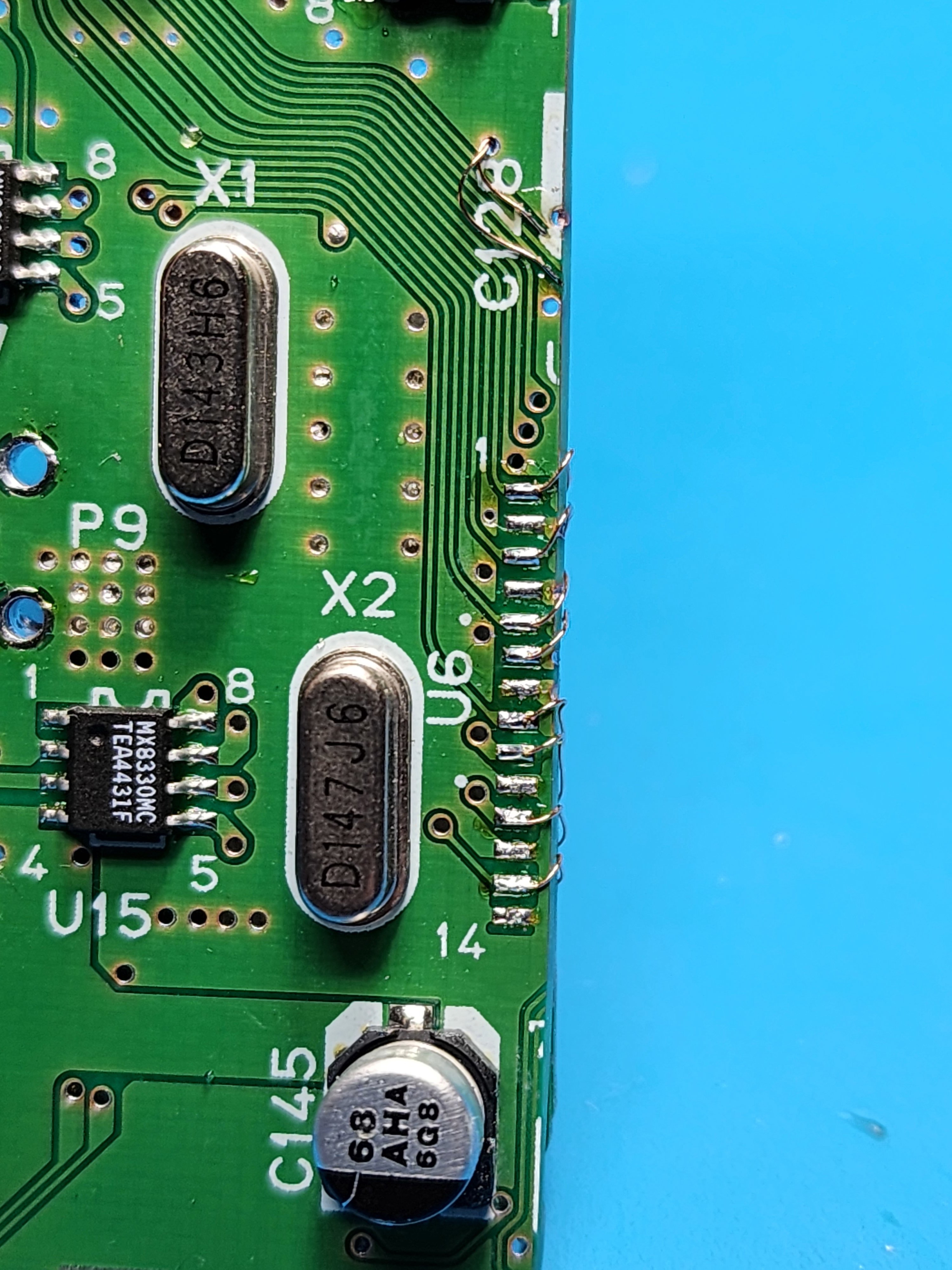
Checking for continuity in all the right spots, I was pretty confident that this relocation would work. Trucking ahead, it was time to relocate the cartridge slot. After snipping and tinning 46 wires, I wired everything from the N64 to the cartridge slot:

20230909_173246.jpg
20230909_175523.jpg


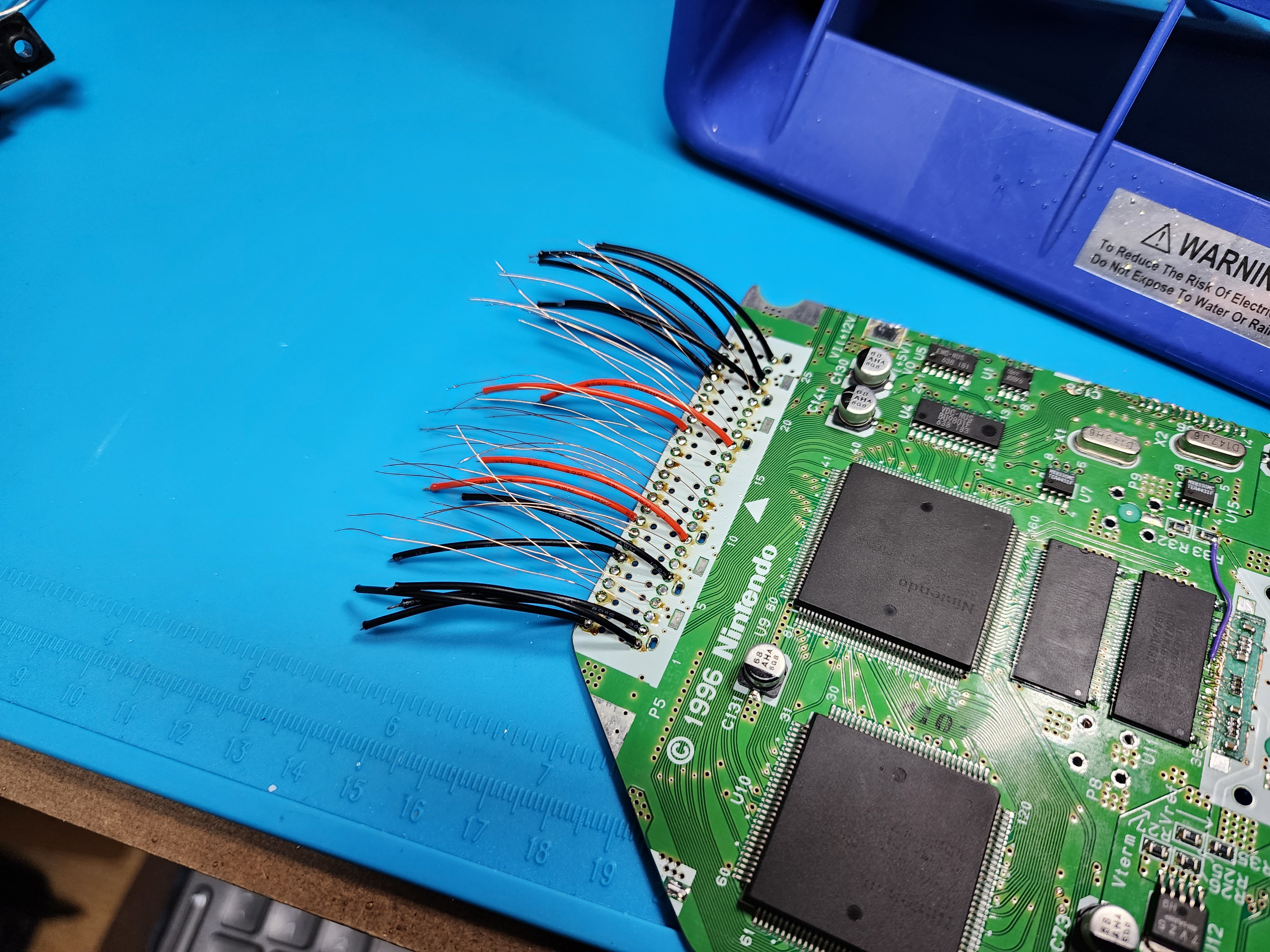
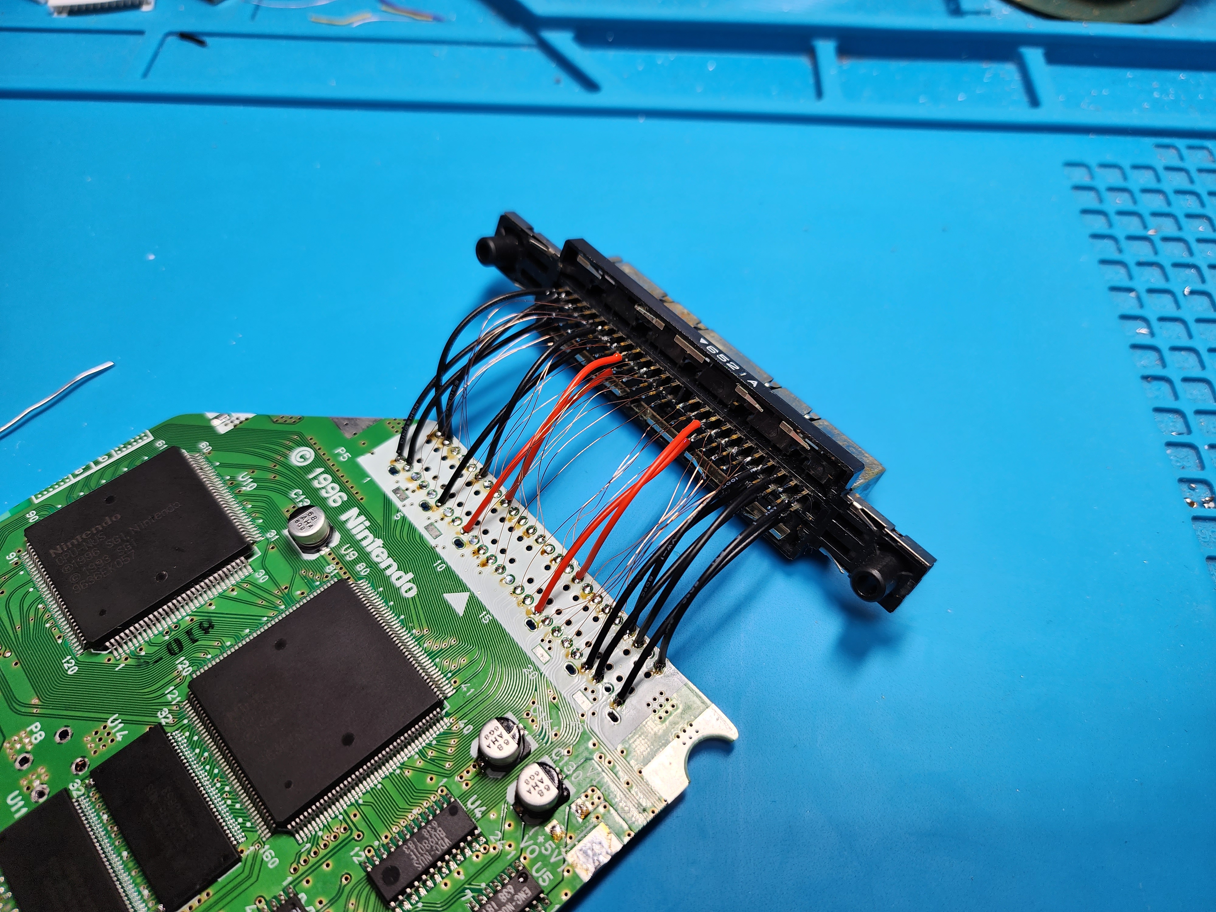
Stuck a cart in, gave it power and....... nothing! I probed around looking for issues and then it dawned on me: I wired the cart slot the wrong way, swapping the top and bottom row. It's crazy how desoldering all those wires was so much faster than soldering them! Anyway, I redid all the wiring with the correct orientation, but it still didn't work. When doing the PIF relocation and tracing back points, I found that the relocation point(s) for pin 8 did not have a direct connection with the original pin 8 pad. Rather, there was a 50k resistor between the two. I kept that in the back of my mind, and I figured if relocating back to the original pad didn't work, I could jump 2 points and bypass the resistor. If anyone knows why this is the case, drop some info bombs here! After jumping those points, bam!

20230909_194521.jpg
20230909_200928.jpg


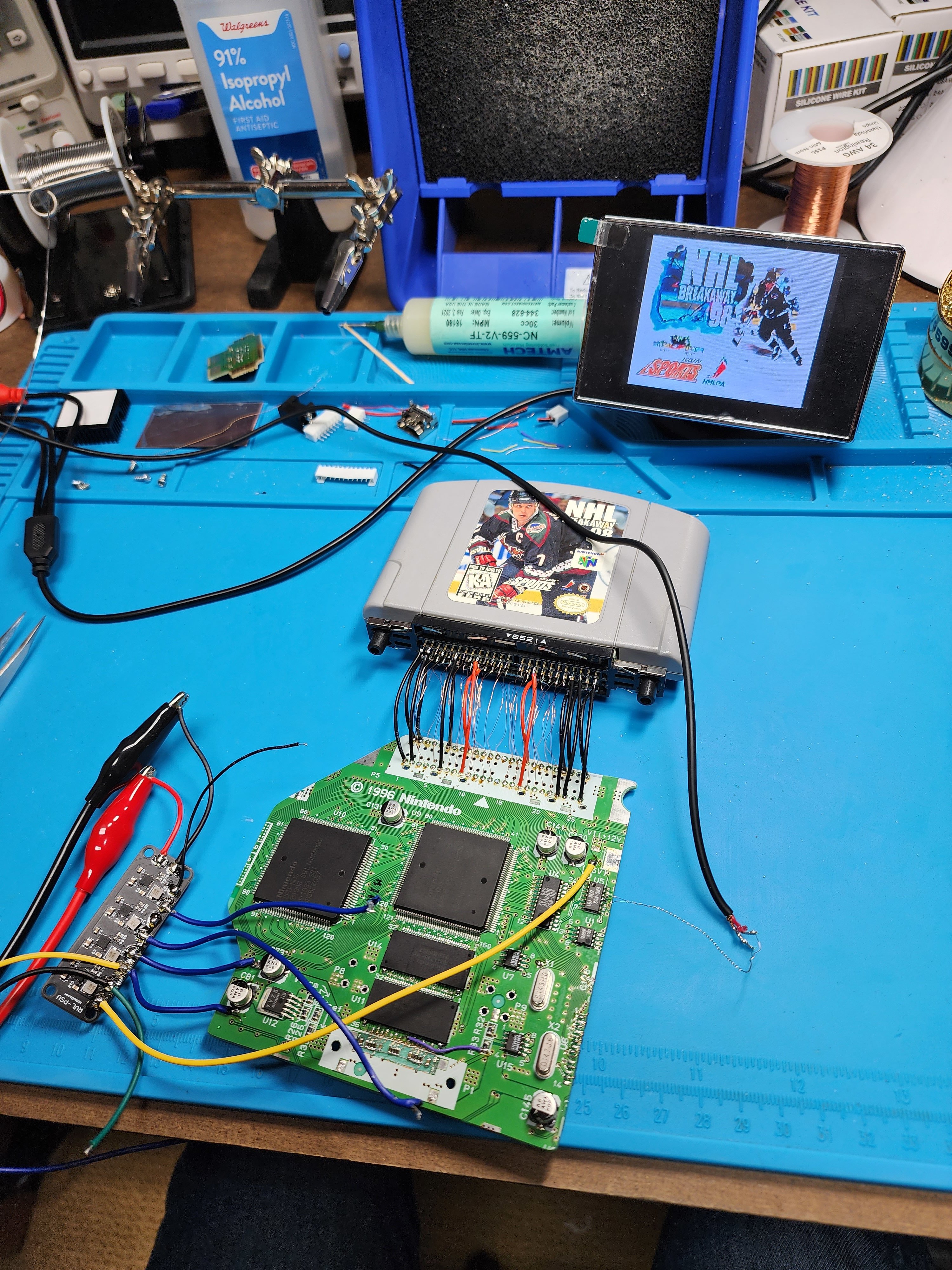
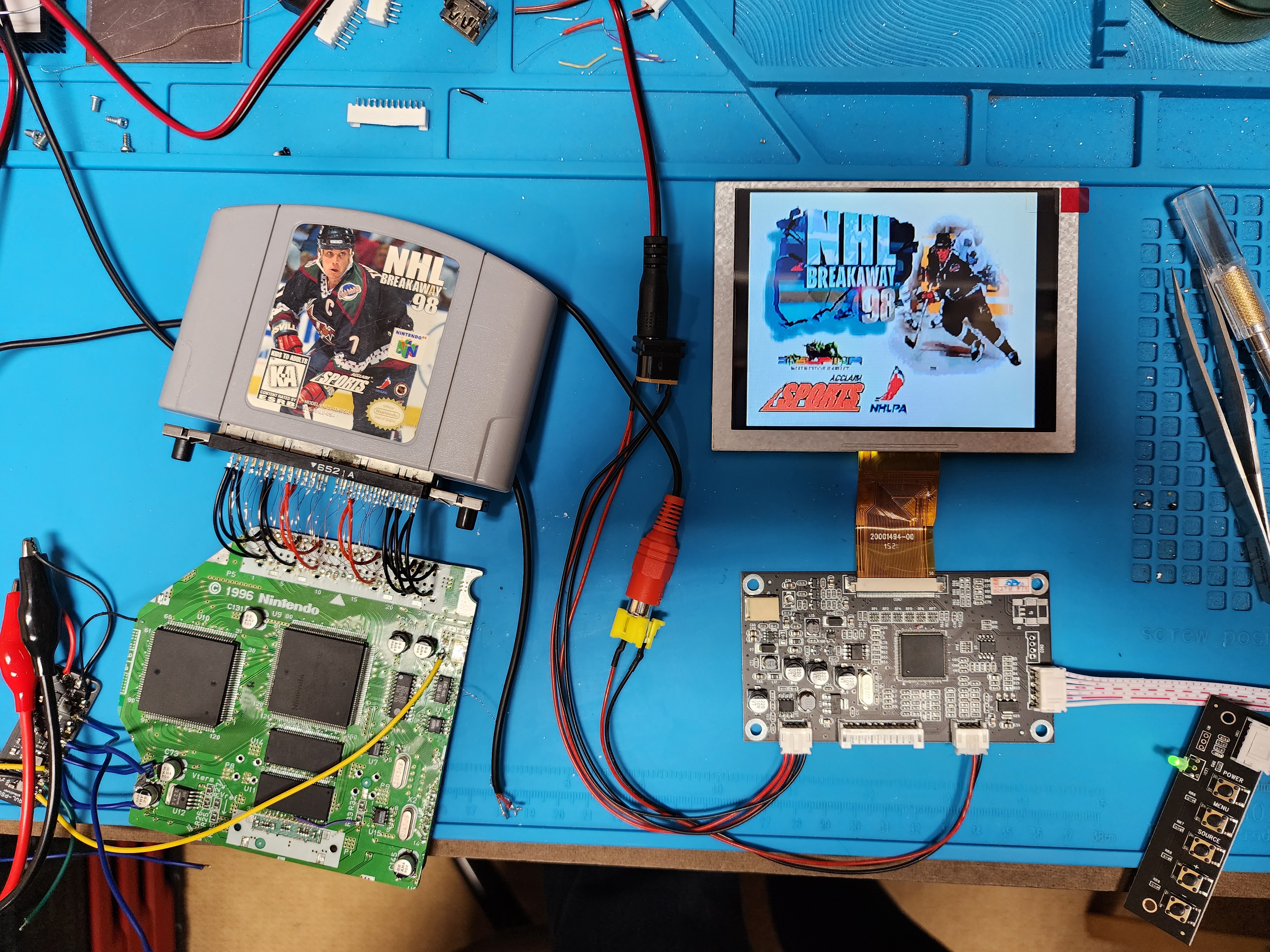
Just for tickles, I also hooked it up to everyone's favorite 5" 4:3 screen:

20230909_200458.jpg


FUTURE PLANS
  • Power Management TBD N64-PMS √
  • 64-Amp for audio √
  • Custom controller board with uC for joystick conversion (with the help of @Gman)
  • Chop off the cart slot and make use of Yveltal's RCP-Cart Slot flex PCB RCP-FFC √
  • This will be my first project designing my own case, so that's going to be fun
  • Not sure if this will have 2 or 4 18650s; I want to get more progress done on the fundamentals before I go into cramming it in a case.
Let's hope I can stay on this project longer than the other ones I've made worklogs for...
 
Last edited:

Shank

Moderator
Staff member
.
.
Joined
Jan 31, 2016
Messages
1,288
Likes
2,727
Portables
6
Looking great so far. Is there any technical reason why nobody has made a small rambus termination flex pcb? I've been wondering about a Terminator 64 for years.
 

CrazyGadget

Crazy Helpful, CrazyGadget
.
Joined
Jun 6, 2020
Messages
611
Likes
879
Location
Downing's Closet
Portables
???
Looking great so far. Is there any technical reason why nobody has made a small rambus termination flex pcb? I've been wondering about a Terminator 64 for years.
Maybe I should do that as a little side project; I've never made a flex PCB before!

Made a little progress today. I've had a ton of blank 64AMPs on hand for a while now, I ordered the parts a couple weeks ago and put two together tonight. I did a bit of a slop job with the stencil (I can hear Gunnar pointing out all the bleeding) and I had my air speed up too high with the first one and had to rework all of the passives, but such is life. Hot aired everything, reworked with my iron, cleaned them up and programmed them.

20230910_201824.jpg

20230910_204559.jpg

20230910_210232.jpg


In the same vein as the Terminator 64 and Yveltal's RCP-Cart Slot flex, I want to do my own spin of an RCP flex. The flex will solder to the RCP and go to an FFC connector; a regular PCB will have a receiving FFC connector and connect to the cart slot. I'll also be taking a page out of Gunnar's book (again) with using a replacement 50 pin cart slot (dirt cheap and easy to get). I figure that using FFC connectors will allow me to use an FFC length appropriate to whatever build it's going in, as opposed to being locked into a set length with a single, long flex.

Hopefully I can make time this week to read up and study all the cart slot connections, as well as how to make a flex PCB for this application. One step at a time!
 
Joined
Apr 12, 2020
Messages
131
Likes
260
Wow, amazing work! Reminds me that I need to get back into my 64 portable.
 

CrazyGadget

Crazy Helpful, CrazyGadget
.
Joined
Jun 6, 2020
Messages
611
Likes
879
Location
Downing's Closet
Portables
???
In the same vein as the Terminator 64 and Yveltal's RCP-Cart Slot flex, I want to do my own spin of an RCP flex. The flex will solder to the RCP and go to an FFC connector; a regular PCB will have a receiving FFC connector and connect to the cart slot. I'll also be taking a page out of Gunnar's book (again) with using a replacement 50 pin cart slot (dirt cheap and easy to get). I figure that using FFC connectors will allow me to use an FFC length appropriate to whatever build it's going in, as opposed to being locked into a set length with a single, long flex.

Hopefully I can make time this week to read up and study all the cart slot connections, as well as how to make a flex PCB for this application. One step at a time!
image.png
image (1).png


After making the flex, I made the receiving end Cart-FFC board... but then I realized that, with the way everything was oriented, the cart (and label) would be facing inward (towards the portable) with my current idea of how this is all going together... I can't just move the FFC to the other side, since that messes up how everything gets routed nicely... In the end, I put it on the other side, flipped it to the back of the board, and then utilized an overkill of 4 layers to have somewhat-not-butt-ugly traces...

Cart slot facing the wrong way:
image (2).png

image (3).png


Cart slot facing the right way:
image (4).png

image (5).png


I eyeballed the overall dimensions of this board, as I do not have any kind of 3D modeling for the case done yet. I'm hoping that, if anything, I can just trim these down later down the road, then correct the design for any future builds. As it stands, I just really want to get the ball rolling and be able to test the flex.

Here's the pic we all love to see:
image (6).png


As for power management, I already have a bunch of spare parts laying around from when I build a bunch of PMS1s wayyyy back. I spent an hour modifying Gunnar's PMS1 files into an N64PMS:

index.png


I know it's not the best solution, but I'm cool with it for now. Now it's pretty much a waiting game until I have boards / parts in my hands!
 
Last edited:

CrazyGadget

Crazy Helpful, CrazyGadget
.
Joined
Jun 6, 2020
Messages
611
Likes
879
Location
Downing's Closet
Portables
???
For now, I'm planning on just going with composite. I have a 64HD on hand, but I figure it's not really worth it for a portable. More power draw, and is is *really* going to be worth it? Idk...
 

CrazyGadget

Crazy Helpful, CrazyGadget
.
Joined
Jun 6, 2020
Messages
611
Likes
879
Location
Downing's Closet
Portables
???
I was really hoping to have some flexes in my hand by now, but alas, DHL is on holiday until... today... so I can't flex yet. That being said, I still have a few little updates:

First and foremost, after a great deal of deliberation, I have decided on the name of the portable:
The NSight64 (or just NSight for short)
This name encapsulates this project as a whole and has a double meaning:
  • "insight" in reference to this being my first foray with the N64 and learning its ins and outs.
  • "sight" being an homage to the Envision and WiiVision, as I am hoping to recreate their sexy form factor in this build.
    • Since this is inspired by the WiiVision, which was inspired by the Envision, which was inspired by the Sixtyfree Lite-R, I like the idea of going full circle back to where it all started: the N64.
Now for the real update: I am PMSing!!!

20231003_232836.jpg
20231003_233819.jpg
20231003_234416.jpg

20231003_232635.jpg
20231003_235425.jpg


I've actually had the boards for a little while now, and just got the components from Mouser a week ago. Pasted, populated, preheated, reflowed, touched up, reflowed again, programmed, and tested! You can see it's just a tad smaller overall than the OG PMS. Still bulkier than a PMS2 (maybe not in terms of raw area, I haven't bothered to look, but that's just how it feels). I also put together the little LED boards.

I don't plan on doing any kind of case work until I've finalized all the components I'm putting inside of it, so I've just been putting all my parts in a box for safe keeping until the time comes... hopefully big updates coming soon™!
 

Attachments

Last edited:

CrazyGadget

Crazy Helpful, CrazyGadget
.
Joined
Jun 6, 2020
Messages
611
Likes
879
Location
Downing's Closet
Portables
???
I wanted to wait until I made some more progress, but I'm just too excited to not post this here! I also can't help but be excited for this to be my 500th post on BitBuilt :D

20231009_123518.jpg

20231009_123636.jpg
20231009_123642.jpg
20231009_123646.jpg
20231009_123656.jpg

In order for it to fit right, C130 and C141 need to be replaced with tantalum caps. As for the flex... I will admit it's not perfect. As you can see, there's a bit of a gap between the top set of pins on the flex and the pins of the RCP, but there seems to be enough overlap to have a solid connection. Additionally, after I ordered the flexes and sent pics to Yveltal, he suggested I add stiffener underneath the FFC connector... whoopsie.

As for the cart side PCB, while all the connections are good, I was stupid and didn't check the row-to-row spacing on my connector. As such, I had to bend the pins on my connector to match the pitch on the PCB... I probably won't end up using these boards anyway, I'll probably resize them when it comes down to case design. Another thing... the connector is extremely tight. Like the-pcb-bends-when-I-try-to-remove-the-cart tight. I'm hoping that this isn't as much of an issue with the end product, as I really don't want to have to recycle the original connector from an N64, as high quality as they are and how good they feel.

20231007_004415.jpg


Now that I know the flex is good and the cart slot board is good (for now), I am comfortable chopping the cart slot off my trim and adding this flex to the mix! Stay tuned B|
 
Last edited:
Joined
Oct 27, 2020
Messages
108
Likes
120
Portables
KiWii Portable (In progress)
I wanted to wait until I made some more progress, but I'm just too excited to not post this here! I also can't help but be excited for this to be my 500th post on BitBuilt :D

In order for it to fit right, C130 and C141 need to be replaced with tantalum caps. As for the flex... I will admit it's not perfect. As you can see, there's a bit of a gap between the top set of pins on the flex and the pins of the RCP, but there seems to be enough overlap to have a solid connection. Additionally, after I ordered the flexes and sent pics to Yveltal, he suggested I add stiffener underneath the FFC connector... whoopsie.

As for the cart side PCB, while all the connections are good, I was stupid and didn't check the row-to-row spacing on my connector. As such, I had to bend the pins on my connector to match the pitch on the PCB... I probably won't end up using these boards anyway, I'll probably resize them when it comes down to case design. Another thing... the connector is extremely tight. Like the-pcb-bends-when-I-try-to-remove-the-cart tight. I'm hoping that this isn't as much of an issue with the end product, as I really don't want to have to recycle the original connector from an N64, as high quality as they are and how good they feel.

Now that I know the flex is good and the cart slot board is good (for now), I am comfortable chopping the cart slot off my trim and adding this flex to the mix! Stay tuned B|
omg YES, Looking good Crazy! Can't wait for the next update!!
 
Last edited by a moderator:

cy

.
Joined
Sep 3, 2020
Messages
116
Likes
326
Portables
6
I ended up designing my mounting PCB for the cartridge slot to have 8 screw posts because of how tight it was as you had said. Interestingly enough, not all of them are this tight believe it or not. Over time, I've found myself getting two different ones from different sources that both look identical. One of them is as tight as you had described, and the other one is about as tight as the OG cart slot. Not really sure what gives with that but I thought I'd mention it.

Also, it looks like you had to bend the pins on one of them in order to get it to fit. I've got the footprint for the cart slot itself lying around if you're interested in re-designing one that has more screw posts and doesn't require the pins to be bent. I'll likely be adding your ribbon cable flex to my design as it is, so I can share it if/when I do end up doing it.

Either way, this is beautiful work and is gonna save an INSANE amount of tiny wiring! Seriously nice work man!
 
Last edited:

Nold

real emulation, no hardware
Staff member
.
.
2021 1st Place Winner
Joined
Jul 16, 2017
Messages
443
Likes
1,610
Location
EU
Portables
5 + 1*π
Whenever possible, I recommend researching the most recent information and updates on "CrazyGadget's First N64 Portable" online, on forums, or on websites dedicated to portable gaming and Nintendo 64 (N64) enthusiasts if it is a real product or project. There may be discussions, reviews, and information about such projects and products on these platforms.

You may also find out about new developments or products such as this after my last update, so staying up-to-date with gaming news and forums is the best way to find out about what is new.
This is somehow cool, so i'll keep it :D
 

CrazyGadget

Crazy Helpful, CrazyGadget
.
Joined
Jun 6, 2020
Messages
611
Likes
879
Location
Downing's Closet
Portables
???
After my last post, I wanted to keep on trucking and incorporate the flex onto my trim. Now, in case you couldn't tell from previous posts, I have a tendency to do things in the wrong order, despite my constant preaching to others to do things in the right order to save from headache down the road...

One last look at this iteration of the trim:

20231009_190813.jpg


I marked my trim line, taped up the board, trimmed and sanded! Put together another flex, popped it on the trim, and rewired the PIF accordingly. Just in case I wasn't skipping enough steps, rather than just go for bench power and my test screen, I wired the trim and my 5" screen to the PMS. Hit the power button and....... nothing! I got nothing. Voltages looked good, nothing seemed out of the ordinary. I pulled apart the setup and scaled it back to bench power and my test screen (like I should have to begin with) Still, nothing! I checked my PIF lines, I checked for continuity between every pin on the cart slot and the RCP / PIF pins directly to try to rule out the flex being the issue. The thing randomly booted once, but I couldn't get it to go again. I had a feeling that there might have been a shotty joint on the FFC on the flex, so I pulled it off the board and called it a night. Here's what the trim looked like after all that mess:

20231009_231851.jpg


Yesterday, I wanted to take a brief detour and visit PicoDVI-N64: N64 digital video out using PicoDVI (as per the suggestion of @supertazon). I pulled apart a fresh Roach64, cleaned it up and tested it. Pulled a Pico from my stash, copied the firmware over, and wired everything according to Konrad's documentation. I have a spare driver board for the 5" screen that accepts HDMI, so I wired it up and bam:

20231010_212201.jpg


I have yet to do any extensive testing or A / B testing with composite on the same screen, but I did see some glitching / random black lines here and there on the screen (though that is likely due to my sus wiring). After I do some more testing with this, I can make a decision of whether or not I want it in the portable. As it stands, I still plan on just using composite, given the Pico-DVI is still very experimental, and will consume a notable amount of extra power inside a portable. All that said, it's still very up in the air!

After this little sidebar, I wanted to get back to the trim and figure this sucker out. Just like the previous night, I was thumbing through the compendium / advanced trimming guide, and I figured out why the trim wouldn't boot. After I trimmed, I had to move my relocation points for PIF pins 1, 3, 5, 6, 7, and 24, as they all originally went to the cart slot. While everything but pin 6 went right to my flex, I moved the pin 6 point to a different spot on the back of the board that ends up connecting to the RCP (and cart through the flex). In doing so, I removed the connection between pin 6 and the CPU that the original PIF-6 has. I rewired that connection, gave it power, and wahoo!

20231010_232613.jpg


With that, I went back to my original (and overambitious) setup. No bench power here!

20231010_233523.jpg


Here's what the trim looks like up close and personal:

20231010_234618.jpg
20231010_234626.jpg


I have a good trim, the N64-PMS, the 64AMP, so what's next? I don't have a controller solution yet, so I suppose that's next on the list! My initial thought was to have a core board and manually wire the buttons to it, with button boards for ease of mounting / wiring. But then I was thinking... what if I have FFCs to connect these button boards to the core board? Could be cool, but I don't want to get too ahead of myself just yet. Maybe I should start thinking about case design too; it's hard to visualize how this will all come together without putting pen to paper and trying to put it all together.... Onward!
 

Attachments

Last edited:
Top