Hello everyone,
I’m working on a Wii portable (Ashida) using a 4-layer trimmed board, PMS-2.., and RVLoader.
It had been working perfectly for almost a year, but after I completely disassembled it to install new batteries, the screen started showing strange colors.
The screen board I’m using is a PCB80050V9 from 4LayerTech.
The console itself boots fine, RVLoader runs perfectly, and everything else (power, audio, USB, etc.) works as expected.
The only problem is a strange color issue on VGA.
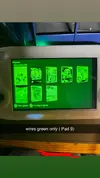
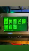
each color works perfectly on its own, but when all three are connected, the image turns green instead of white like the green channel is overpowering the others.
look at pics !
That’s confusing because the signal clearly passes, but its impedance doesn’t match the others. Could this mean a partial failure inside the AVE-RVL chip?
If anyone knows the expected resistance values for these pads, or has already dealt with a similar issue (each color OK alone but not when combined), I’d really appreciate some help or advice.
Thanks in advance!
I’m working on a Wii portable (Ashida) using a 4-layer trimmed board, PMS-2.., and RVLoader.
It had been working perfectly for almost a year, but after I completely disassembled it to install new batteries, the screen started showing strange colors.
The screen board I’m using is a PCB80050V9 from 4LayerTech.
The console itself boots fine, RVLoader runs perfectly, and everything else (power, audio, USB, etc.) works as expected.
The only problem is a strange color issue on VGA.
Current wiring
The wires from the screen board go to the Wii as follows:
- Pad 11 (Pr / B) → twisted with GND
- Pad 9 (Pb / Chroma / G) → twisted with GND
- Pad 7 (Y / Luma / R) → twisted with GND
- H-Sync and V-Sync twisted together with a ground wire
Color tests
| Connected wires | Color on screen | Result |
|---|---|---|
| Red only | Red | ok |
| Green only | Green | ok |
| Blue only | Blue | ok |
| Red + Blue | Magenta | ok |
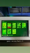
| Red + Green | a bit of red, but green clearly overpowers it. | idk |
| Green + Blue | Cyan | ok |
| All three (R + G + B) | Green | Problem |
look at pics !
Resistance measurements
Without screen wires connected:
- Pad 11 (Pr / B) ↔ GND ≈ 37 Ω
- Pad 9 (Pb / Chroma / G) ↔ GND ≈ 3 MΩ
- Pad 7 (Y / Luma / R) ↔ GND ≈ 37 Ω
- Pad 11 (Pr / B) <--> GND ≈ 75 Ω
- Pad 9 (Pb / Chroma / G) <--> GND ≈ 50–70 Ω (variable)
- Pad 7 (Y / Luma / R) <--> GND ≈ 75 Ω
That’s confusing because the signal clearly passes, but its impedance doesn’t match the others. Could this mean a partial failure inside the AVE-RVL chip?
If anyone knows the expected resistance values for these pads, or has already dealt with a similar issue (each color OK alone but not when combined), I’d really appreciate some help or advice.
Thanks in advance!