Worklog OME6A - The 6-layer OMEGA

Lazr

.
Joined
Oct 3, 2023
Messages
106
Likes
295
Location
WA
Portables
Zero! Micro console gang 4 life!
There is no point in this existing, but it was fun to work on alongside @Mrak408! Really put my Wii knowledge to the test - which isn't very much compared to others, but it's just enough to get a working trim!

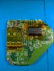
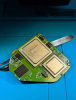
Here's the real OME6A we've been yearning for, but never had until now:
1734038600562.png
1734038624347.png


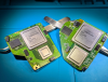
And proof that it does work:
1734038692248.png


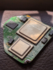
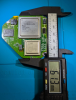
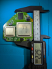
The crazy part is that its not much bigger than a 4L OMEGA:
1734038756345.png

I could have cut in a little bit more above the RAM, if it wasn't for my U10 relocation (I could have moved it but I just didn't bother to).

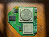
AVE daugherboard was taken from another 6-layer Wii. I somehow killed it prior, so there was no real loss here.
NAND daugherboard was taken from a Wii U. I had a few NAND/eMMC daugherboards laying around and just cut off the eMMC part. I did swap the TSOP, no NAND flashing here.

I do not see any portables using a OME6A considering the higher power draw compared to 4 layer boards, but maybe its useful for a micro console?

If anyone ever decides they want to do a OME6A, feel free to post them here! Do note that it's the same story as all OMEGA trims - rite of passage. Peeps can also see my progress in the discord.
 
The naming scheme is a nice touch. I approve.
 
Oh I forgot to mention, massive props to Shank for sharing his 6 layer board scans. :)
 
Incredible work! Can you please share where you got the board scans? I want to try this with some 6 layer wiis I have
 
Shank was kind enough to upload a .zip file of them to a folder on my GDrive. The shanks.xcf should have the 5 layers that have been scanned mostly aligned. It's not complete, but its good enough.
I suppose I should also apologize for not linking them until now, just never crossed my mind.
 
Thanks! I will post my progress if I can succesfully do this trim
 
Before I start yapping, I know I'm several months late. Lazr and I started the quest at around the same time in December, however, I had hit a roadblock which stopped me from fully completing mine - that being the dreaded "black screen". To skip over the details, I had put the project away for 7 months due to a single resistor; the I2C pullup for the AVE. Most of my time went to redoing the AVE relocation and rewiring the nand while completely overlooking that tiny detail. But alas, I had gotten proper video out on through composite. Unfortunately, I was about to hit yet another roadblock. The Wii's USB phy requires 3.3v to be provided to 3 different vias, presumably one for each USB controller inside the vegas. In Lazr's trim, she had quickly discovered that the supply traces going to those vias were cut due to the trim; simply soldering a single wire to all of them. This method had allowed boot, but what was unknown at the time was that the USB wouldn't work on the Ome6a. Since it wasn't tested, It was understandably presumed that the trim was fully operational. In my case, I was also completely unaware about the USB issue - until I encountered it. Without going through the painful details, I had resorted to every known USB troubleshooting method: Reformating, using different drives, swapping the USB pair, trying the other USB port, even attempting to sniff the USB with a Pico LA (Which wouldn't even work for 2.0 highspeed lol). I had gone back and remembered about the traces that supplies power to their respective USB controller. Each trace had it's own filter circuit, comprised of a ferrite, a feedthrough cap, and a large MLCC. So basically, I relocated every component from the filter circuit in an unorthodox, groteqsue bodge (originally didn't include the large caps).
1749931711312.png

This... Didn't do much. But after a few hours of banging my head against a wall, I had remembered about a single resistor which was located nearby. R70 is a 12kohm pull-down resistor used for "USB_RCOMP", resistance compensation.This resistor is usually located under the Hollywood in a 4-layer, but it was outside the cut on an Ome6a. Omitting this resistor messes with the controller's impedence matching, resulting in the USB problems I listed. So I simply relocating the resistor back (along with the large decoupling caps for good measure), and...

1749932139152.png
1749932079818.png

ignore the soggy image

The first fully working Ome6a. (more pictures attached below)
1749932374802.png

I'm, again, skipping over many details (i.e: how I got the dreaded omega U10 problem, whether or not the USB phy filter passives were ever really needed, how I dug to the voltage layer twice to relocate 2 tantalums (and how the 3.3v one prob isn't needed either), how this trim would look with other 6 layer revisions, whether or not the CPU passives near the bottom are needed, possible room for an FD-Ome6a, etc.) But I'll leave that to whoever is insane enough to attempt this trim. It took me 7 months to relocate one resistor, then 2 days to relocate another, hopefully that won't happen again now that this information is available.

1749932862897.png


As a bonus, I went ahead and tested how the trim ran with the GC nano V2 cooler (a 55mm heatsink with a 5v fan). After 4 hours of a SSBM match, the Wii barely felt warm to the touch. In fact,the 1v regulator felt hotter than the heatsink or back of the Wii (unsure if it's the inductor or reg itself causing it, but understandable due to the higher current draw). The barebones Ome6a drew 5v ~2.1 amps, meaning we could potentially get away without PD. I'm interested in possibly designing a micro around the Ome6a, since there doesnt seem to be many advanced builds for 6 layers, meanwhile the 4 layer omega has like 10 new projects being made for it lol. If I do end up designing board and flexes for this, I'll include the USB filter circuit on it just in case.(Atleast, a more simplified version of it, like the one present on 4 layers)
 

Attachments

  • 1749932031595.png
    1749932031595.png
    22.4 MB · Views: 109
  • 1749932385105.png
    1749932385105.png
    14.6 MB · Views: 89
  • 1749932397292.png
    1749932397292.png
    19.1 MB · Views: 107
  • 1749932419197.png
    1749932419197.png
    26.4 MB · Views: 106
  • 1749932436345.png
    1749932436345.png
    10.4 MB · Views: 104
  • 1749932445330.png
    1749932445330.png
    15.2 MB · Views: 84
  • 1749932455533.png
    1749932455533.png
    13.8 MB · Views: 100
  • 1749932467080.png
    1749932467080.png
    13.5 MB · Views: 96
Last edited:
I got bored and made another lol
1768853830898.webp
1768853840920.webp
\

A few differences from my original one:
- 6L-NANDFlex!!
- deadbugged AVEFlex (maybe someday ill actually commit to design for 6L but for now this is fine)
- R70 relocated (instead of nuked)
- U10 is using the "standard" U5 footprint relocation
- CPU passives bypassed

The 6L-NANDFlex can be found here. I wouldn't recommend only relying on the castellation for mounting and would hold it down with some sort of glue.

The AVEFlex was actually really easy, but that's probably because I spent the time to highlight which vias had to go where on the flex with my scans:
1768854240571.webp
1768854265739.webp

Again I didn't bother to wire up I2S because I doubt I'm going to use this in literally anything except as showpiece.

R70 relocation I did forever ago just because I wanted something to do (C128/C129/C130 capacitor bypass is also pictured here)
1768854327480.webp


U10 at U5 on 6L trims only works if you don't cut through this portion of the 3v3 pour:
1768856075285.webp

The OM6 guide just barely touches the corner, but on more extreme trims like this it wont work unless you wire 3v to pin 5 of U10:
1768854739518.webp

The board was still booting before I realized this but I had to manually reset the Hollywood otherwise nothing would work properly.

Not much to really note here. its just two capacitors, a ferrite bead, and a 2ohm resistor. Under the mask is just a wire so here's a representation on the scans
1768857708781.webp
1768857772281.webp


IDK where else to document this but here goes:
While I was working on this, I was using Yveltals bistro to power the board since the PSU-Plus was being used elsewhere.
It generates all the necessary voltages for it to boot (1v/1v15/3v3) but instead of 1v8, it generates 1v5 (because this is what the Wii U DRAM is ran at).
This undervolt seemed fine when I initially tested it, but it wasn't really a thorough test. Just saw rvloader bootloader and called it a day.
Come to actually testing it and..

At first I thought the GPU was kicking the bucket (wouldn't anyone?), especially since there was no heatsink for most tests and it was being left on for a few minutes at a time.
What really almost nailed the coffin was that it happened on both screens I was using for testing.
At first I thought that maybe it was the batteries because they were really low charge. Put all 4 of them in parallel and the issue persists..
I don't know why, but I remembered that the rail was being undervolted. This was the point where i just grabbed the PSU-Plus and tried it. (not so) crazy thing is that was the issue. So relieving.
Moral of the story is uh, don't undervolt like a maniac I guess.

Other memes include:
Running both 1v and 1v15 off the same reg (probably only possible on regs that are rated for at least 4 amps?)
1768856233716.webp

It didn't last for very long since I didn't want to introduce any issues later by undervolting the PPC.

So yeah there's 3 ome6as now. Maybe next meme trim will be the circle trim? 6L or 4L though.. :rothink:
 
Last edited:
Back
Top