What's new

Worklog Wii Classic Edition

Joined
Jan 15, 2020
Messages
62
Likes
55
Recently I saw Project Short Stack by Loopj and I really love how cute having a little console is. I considered making one myself, but doing so would require an OMEGA trim which is beyond my capabilities, at least at the moment. Enough time has passed since my spectacular failure with the Wiiclipse that I feel like I am ready to tackle another project, this time less ambitious.

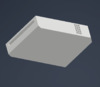
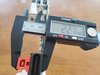
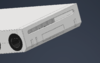
What I propose is making a half scale Wii using the simpler OMGWTF trim. This would be half the size in all dimensions and one eighth the total volume of a normal Wii. This scale probably doesn't match the scale of the official Nintendo classic edition consoles, but names like the Wii Mini, Wii Micro, and Wii Nano are already taken.

wii classic edition.PNG

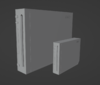
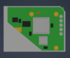
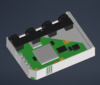
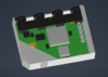
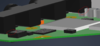
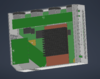
This currently is just a mock-up and I haven't started any cad yet, but I think it should just about be able to work. If I can't exactly do half scale then the goal will be as small as possible while keeping the Wii proportions.

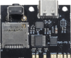
I plan to keep it simple. I just plan to put a usb-c port on the back for power (using the PMS PD 3) and an HDMI port for video (using the ElectronAVE Kit) on the back of the console. I plan on using the RVL-PSU for powering the Wii because something like the RVL-PMS-2 would be overkill for this project (also I already have an RVL-PMS laying around). I might consider using something else for the voltage regulators because as far as I can tell the RVL-PSU cannot be purchased anywhere, and I would like this project to be ewasily available to anyone who wants to use it, and hopefully beginner friendly.

PMSPD3_1024x1024.pngIMG_2689_08bad5d7-e1b5-4666-85e5-32c0faefaa60_540x.png20240721_224835.jpg

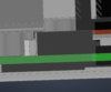
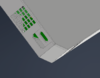
I do want to additional details that would make the build more complicated, but I think it will be worth it. First of all, I am going to try and make the buttons up front work as buttons with the power and reset buttons functioning as intended, and the eject button working as a sync button. Secondly, I am going to try to add Gamecube ports to the side, just like a real Wii. I hope I can squeeze full sized ones in there with a bit of trimming, but if it turns out there isn't enough space when I start cad, I will juse use headphone jacks like GC Nano by Wesk and CrazyGadget or The World's Smallest Gamecube by Madmorda. Lastly, if I can squeeze a blue LED in there to light up the disk ring like in Project Short Stack, I will do it.

Thank you for taking the time to check out my post! Please let me know what you think of the idea and if you have any ideas on how it should be modified or if it's just a stupid project not worth pursuing.

Post note: I just saw that YveltalGriffin is working on another mini wii called the Kawaii. I'm so excited to see how it turns out! Once again it used the OMEGA trim, so I hope I can make something more accessible to me and other members.
 
Joined
Nov 13, 2022
Messages
240
Likes
109
Glad to see someone picking up this project again! A couple months back I attempted making a downsized Wii console myself (funny enough also called the Wii Classic Edition). A OMGWTF trim is the way to go. Speaking from experience, a Noldendo is way to cramped in the case and OMEGA is overkill for anything that’s not designed to fit in your pocket. As long as your keeping this roughly the same size as the other Nintendo Classic Edition consoles, there should be no problem fitting full sized GameCube controller ports along the one side. The only thing I can see giving you a hard time is the inclusion of a PMS-PD. To my (limited) knowledge, there is no documented way of incorporation one of those into a Wii that doesn’t also use the RVL-PMS. Hopefully it’s still possible and I wish you luck with any research/discoveries made! I love your idea of making this is a simply replicateable build, perhaps the next evolution of the Noldendo Micro!
 
Joined
Jan 15, 2020
Messages
62
Likes
55
Ah, so the project name was already taken, but it sounds like you stopped working on your project so I hope you're ok with me using the name. I want to have it run off of a usb-c port, so If I need to use and RVL-PMS board, I'll probably use one of those. Thanks for the feedback!
 
Joined
Nov 13, 2022
Messages
240
Likes
109
Ah, so the project name was already taken, but it sounds like you stopped working on your project so I hope you're ok with me using the name. I want to have it run off of a usb-c port, so If I need to use and RVL-PMS board, I'll probably use one of those. Thanks for the feedback!
lol don’t worry about the name! I never finished the project anyways, so it’s all yours

copyright ownership transferred

Best of luck with everything!
 
Joined
Jan 15, 2020
Messages
62
Likes
55
First thing I wanted to do was get some basic measurements to see how feasible this is. First thing was measuring the Wii. My Dial caliper was too small for the larger measurements, but I ended up with the dimensions of 214mm x 156mm x 44mm. Please let me know if I am off on the measurements, but assuming these are correct, that leaves the dimensions of 107mm x 78mm x 22mm for my project.

20240722_115343.jpg20240722_115242.jpg20240722_114827.jpg

Thanks to the remains of the Wiiclipse, I was able to measure the dimensions of a real trimmed Wii. Not all trimmed Wiis are the same size though, so I’ll have to design some wiggle room. My trimmed Wii comes out to 99mm x 75mm which is just small enough to fit inside a 106mm x 78mm project. For other people that want to try and make this once it’s finished, if they use the trim guide that I designed, they should be able to get a similarly sized trimmed Wii motherboard.

20240722_115028.jpg20240722_115110.jpg

Finally, I wanted to check whether I could fit the full sized GameCube ports into the space. To my surprise, it looks like they will just about fit inside in theory. The standard arrangement of GameCube ports on the wii is 100mm wide and 17mm tall. That leaves just a little bit of wiggle room. I don’t yet know if I can squeeze it in there with the trimmed Wii at the same time, but if I mount the trimmed Wii upside down in the case I think I can get away with it.

20240722_114946.jpg20240722_114914.jpg

I don’t plan on lessening the spacing in-between the GameCube ports. I want to be able to use the ports and board from a real Wii to allow ease of assembly. Also, this spacing is just wide enough to allow wavebird receivers to be placed right next to each other.

I think it would be cute if the smaller Wii used the smaller intake and exhaust vents. The Wii fan is about 36mm, so do you think I could get away with cooling the fan with an 18mm or 20mm fan? Maybe something smaller even.

20240722_115631.jpg

Next time I’ll come back with some cad :)
 
Joined
Jan 15, 2020
Messages
62
Likes
55
So I started working on the cad, and I must say, it is really easy to make something look like the Wii.

it looks like a wii.png

That image doesn’t do a good job showing scale. Here is an image of me trying to position an OMGWTF trim inside of it. Not much room inside. I tried to position the Wii such that maybe I could use the vents, but it just doesn’t line up well. There is a little bit of clipping outside of the case but I think I can remove that section if needed. Also, you’ll see later that it didn’t even matter.

the wii fit in the case.png

Thanks to the Wiiclipse, I was able to use files like the trimmed Wii I made to help me design this. As you can see, the GameCube ports can fit in this design, and the look comically large on this mini little Wii. My idea of mounting the Wii upside down to allow for space for the GameCube ports and their board worked, but I didn’t account for it getting in the way of the cpu and gpu.

comically large gamecube ports.pnggamecube port positioning relative to the wii.png

It was a pretty easy fix, I just had to rotate the trimmed Wii 180 degrees. That way the side with more empty space is aligned with the game cube ports. It still gets a little in the way of the cpu and gpu, but I think it’s not significant. More importantly it clips into the LDO and a capacitor. The capacitors can be removed, but if I remove the LDO I’ll need to use a PSU-Plus instead of an RVL-PSU, so I will try moving the things around and see if I can make some room.

wii rotated 180 degrees.pngit's clipping the ldo and a capacitor.png

Since using the vents on this Wii can’t work the same as on a normal Wii, I was thinking I could intake air from the back vent, funnel it to a heat sync over the cpu and gpu, then fennel it to exhaust out the disc slot. To do this I would need to remove all the capacitors on the trimmed Wii. What do y'all think? And do you have any mini fan suggestions that are good?

Also, I decided I’m not going to try to make a piece that covers the GameCube ports. All it will do is make it so there is a loose piece of plastic laying around whenever you use it, so instead I think I’ll just make a secondary version of the case without holes for the GameCube ports for anyone that decides they don’t need them.
 
Joined
Nov 13, 2022
Messages
240
Likes
109
I’d take a look at the cooling setup of the Ashida, just might be slim enough to fit in your case (at least for the heatsinks). Refer to the Ashida Bill Of Materials for specific part links. In terms of cooling vents, you might be able to design a shroud that directs the air toward your available holes in the shell. I never would’ve thought to use the disk slot as an air vent, but that would be really cool if you could get it to work. Removing the rear capacitors is possible without damaging the trim, and if you are using the ElectronAVE there should be no compromises to video quality either. If you’re planning on making this as accessible as possible, have you considered using a ElectronHDMI instead for HDMI output? The quality won’t be as nice, but it’s a much easier install and only introduces less than a millisecond of latency. Not to mention it’s a good bit cheaper. Nice job with the CAD, forgoing the port cover is probably for the best. Can’t wait to see what you’ve got next!
 
Joined
Jan 15, 2020
Messages
62
Likes
55
I think the big issue with cooling for me is trying not to add any holes onto the case that aren't there on the Wii already. I have a few Ideas for cooling but I would also like to see what ideas people have

I can't find anything called the ElectronHDMI. I assume you mean the ElectronWarp from Electron Shepherd? Maybe. But the assembly for those ports are already wider than the envelope I am trying to design inside of. Maybe if I cut off the sensor bar port. Could be another variation of the design.

20240724_145250.jpg
 
Joined
Jan 15, 2020
Messages
62
Likes
55
ooooh yeah that would be interesting. Is that a full sized HDMI port too? I might just need to make an alternate design for that. I already ordered an ElectronAVE kit.

As for the shell height the target size is 107mm x 78mm x 22mm, so it should be under 22mm, ideally less than around 15mm so I can mount the usb-c next to it
 
Joined
Jan 15, 2020
Messages
62
Likes
55
So I managed to make some space for the GameCube ports so I don’t need to remove the LDO. It’s going to be a tight fit but I think I can get it to work. This came at the cost of shifting the GameCube ports down so they are no longer centered. It’s a small price to pay.

just enough space.pngsadly it is off center now.png

I started adding the PMS PD 3 and the RVL-PSU to the board. It’s satisfying with how well the RVL-PSU fits in right next to the Wii. I also added the heat sink and copper plate thanks to the files I made for the Wiiclipse. It’s pretty easy to see that in this arrangement that using the two normal Wii vents wouldn’t really work. I think maybe I can use one or both of the vents as air intake and then exhaust out the disc slot since that won’t be used for anything.

it's all starting to come together.pngdisc slop capacitors.png

You can see in the picture above that the capacitors on the trimmed Wii are in the way of the disc slot, but I don’t think they are necessary for the function of the Wii so I will remove them to make room for the air vent. Also I need to remove one of them anyway to make room for the GameCube ports.

I also took the opportunity to model the ports onto the back of the case. Doing this reminded me that I have no port for the sensor bar planned. I don’t even know how I would relocate that since it’s attached to the AV port on the Wii. Do you guys have any ideas? I think maybe I’ll just mod a sensor bar to use usb and plug it into my monitor.

the ports.png

Also I’m just realizing that the ElevtronAVE kit doesn’t have a full HDMI port, just a mini HDMI port. I’m going to have to remodel that part, but that is also another inconvenience needing to use an adapter. Oh well. I guess this can’t be perfect, at least not with the first iteration.
 
Joined
Nov 13, 2022
Messages
240
Likes
109
All you need for the sensor bar port to work is 12v and GND. Although honestly I wouldn’t bother including it at all. Just getting a wireless sensor bar would make everything a whole lot simpler. If you are really set on using full sized HDMI, the ElectronAnalog will do the trick.
 
Joined
Jan 15, 2020
Messages
62
Likes
55
yeah I'll make a version for the ElectronAnalog, but i do want at least my personal one to use the ElectronAVE kit.

I have a wireless Wii sensor bar and it sucks. Not only do i have to deal with batteries, but it takes 4 aaa batteries and it goes through them really quickly. This isn't a portable so a usb one will do
 
Joined
Nov 13, 2022
Messages
240
Likes
109
So there will be USB ports on the back? In that case, it might be easier for you to just use that to store your games. In combination with a PSU Plus, that would give you the simplest assembly.
 
Joined
Jan 15, 2020
Messages
62
Likes
55
Well no. I mean just like plug into the usb port of a computer or monitor. It would be hard to fit a usb port on here too (besides the usb-c power port). Also what do you mean by the simplest assembly? I still need a board for usb-c power
 
Joined
Nov 13, 2022
Messages
240
Likes
109
Right, I forgot about the USB C board. You can just order a 12v or 15v PD board on Amazon for like $8. What I meant by simplest assembly was that everything just needs to be wired up and it’ll work. I’m not sure what extra trickery you would need to pull off to get a PMS-PD to work with your RVL-PSU.
 
Joined
Jan 15, 2020
Messages
62
Likes
55
Hm, alright. Which board would be the best to get. I don't want to get something that will potentially break the Wii. Also, I would need to get another one of those sandisk micro sd card adapters. Also then the sd card would be locked in the Wii and there would be no way to access and change files without opening up the Wii, unless I change the design. It does seem like it would end up being more work and more complicated. If the RVL-PSU doesn't work with it, I suppose I can just steal the RVL PMS 2 from the corpse of the Wiiclipse, well. Assuming it still works and didn't get corroded or something.
 
Joined
Nov 13, 2022
Messages
240
Likes
109
That might be a good solution, but you’d have to figure out how to get the RVL-PMS to run off wall power (shouldn’t be too difficult, hopefully). Don’t try this without making sure, but in theory, if you just replace the battery hookups with a power source of the same voltage/amperage, it should reregister it as batteries that are always 100% full (that’s my guess I don’t know for sure). If you want to forgo the PMS PD entirely, you could create a hidden micro SD card slot on the front of the Wii where the SD cart slot normally would be (just an idea that keeps with your clean, vanilla Wii aesthetic).
 
Joined
Jan 15, 2020
Messages
62
Likes
55
I have other plans for the front of the Wii console, but it's an option. Also I am not sure what you mean by replacing the battery hookups. This wont have batteries, and I don't plan on using a PMS unless I have to, unless you are talking about battery hookups ion the PMS PD 3, but that doesn't have anything inside of it to monitor or manage batteries, that's all inside the PMS iirc. I'm not sure. I just feel like it would end up being easier using something more closely designed for this use case. Also I trust it not to explode because it is from people in the community
 
Joined
Nov 13, 2022
Messages
240
Likes
109
You’re right, I just realized my mistake. I forgot that your power input would come through the PMS-PD, not the RVL PMS. My biggest concern is you needing the RVL-PMS to make use of the MUX switching from the PMS-PD. Hopefully you take a look at the documents on 4 layer tech and figure out a solution.
 
Top