Worklog O-Wii First benge portable wii

Benge

.
Joined
May 18, 2020
Messages
200
Likes
676
Location
France
Portables
4 : O-Wii (V1,V2,V2.1)/ BS2
Hello everyone, I'm new on this awesome forum and after a month of research and walking into BitBuilt I start this thread for share my first portable console the O-WII !
The goal is to make a nice thin and clean portable WII.

1 - the choice of custom power supply :
For that I have first see the Custom regulator (PTH08080 ) was very simple to use but WTF the price is very high for just a regulator,
another solution was to use the awesome WII Power Management System but it is dificult to build, the price was correct for the advantage
and time gain but I wanted to see a cheaper solution.

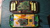
For that solution I have tested the HW-613 very cheap regulator on 7.4V ( 2S 18650 ) :
20200610_174227.jpg


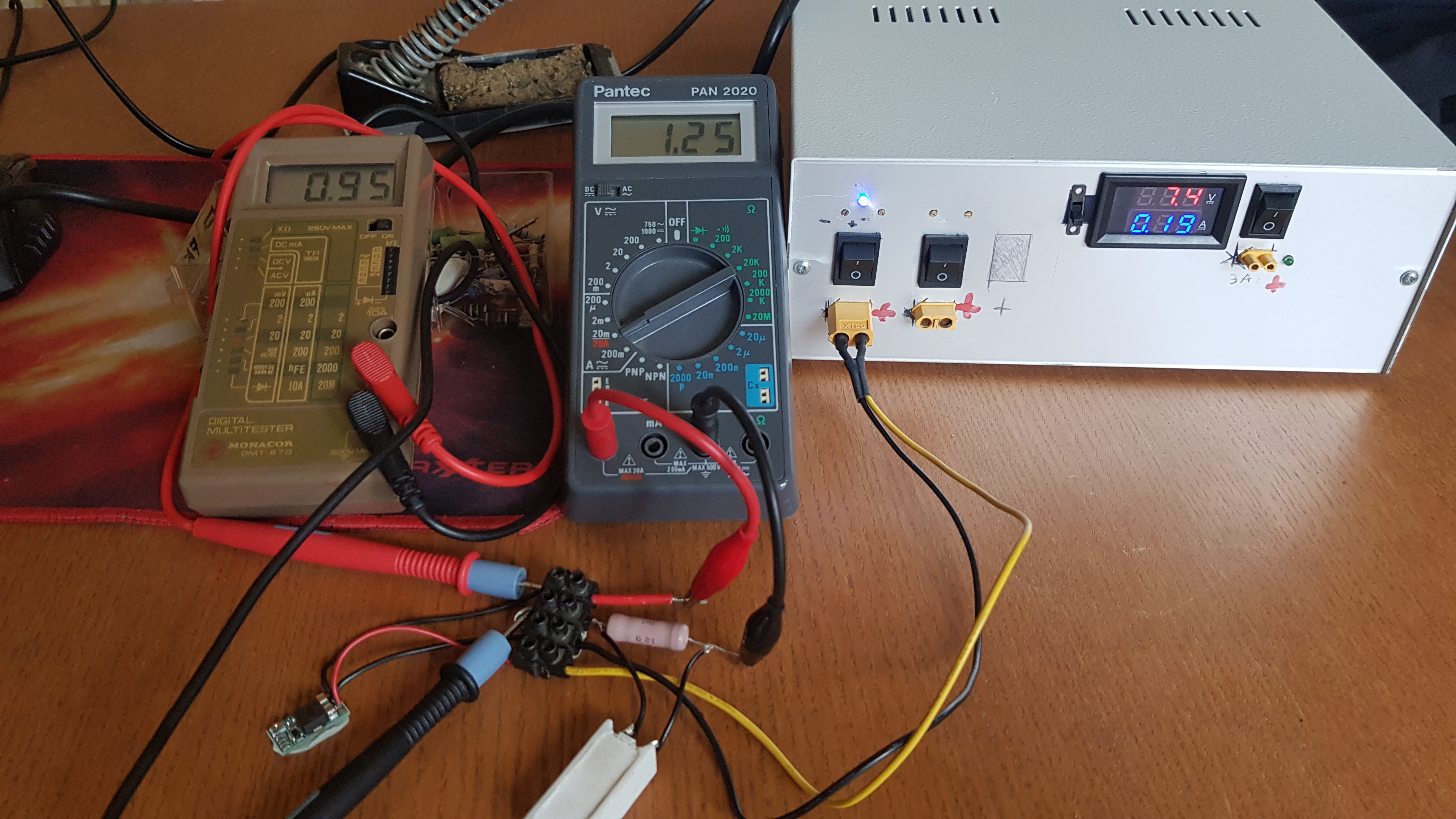
So I tested the efficiency of these regulators at different voltage and normal operating current of the wii
and the result was greater thant I think for this very cheap regulator.
Efficiency cheap regulator.png

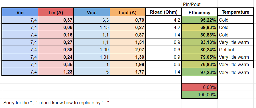
Normally it can go up to 3A (I doubt), if the regulators are stable and can go out 2A with good efficiency and low voltage drop I think it can be a good solution.

Obviously I need to test more and on real condition to watch if these regulator do the job.
Tomorrow more and other tests :)
 
Last edited:
Joined
Aug 2, 2016
Messages
290
Likes
136
Theres a seller on ebay that does 2 pth regs for 15 bucks or so. I bought like 6 off the seller and only one of them had problems.
 

Benge

.
Joined
May 18, 2020
Messages
200
Likes
676
Location
France
Portables
4 : O-Wii (V1,V2,V2.1)/ BS2
Oh thanks, very good price i'm going to watch that.

2 - Wii trim :
My WII is a black WII with RVL-CPU-50 board, it is a 4 layer, perfect !
20200615_161307.jpg


I have relocated the U10 chip to U5 before the trim
20200615_173951.jpg
20200615_174958.jpg

After work I have protect all chip with masking tape and trim the board with dremel.
Then I have sand the edge with smaller and smaller grain.

20200615_2002333.jpg
20200615_200642.jpg

I have tested all the voltage point with multimeter and all are good with no short circuit.
Then I have relocated the bluetooth, solder wire to USB port, RCA video, gamecube controller port and wire all regulator to voltage points.

20200618_184316.jpg


And .... IT WORK !!! :
20200618_183023.jpg


After testing my trimed wii with my regulator, the wii crash very often an the 1.15V regulator become hot.
I think the voltage are not very constant with the power needed for 1.15V
I 'am going to replace this regulator by a PTH, and if it doesn't work I'm going make a RVL-PSU WII PMS because it is very thin and it have all feature needed (charge, good max current values, protection ...).
 
Last edited:
Joined
Jul 13, 2020
Messages
2
Likes
2
Nice work! Btw, your profile picture is terrifying
 

Benge

.
Joined
May 18, 2020
Messages
200
Likes
676
Location
France
Portables
4 : O-Wii (V1,V2,V2.1)/ BS2
Thank you, is this profile picture better?

After a long time without news here is the rest of the build !

Since my cheap regulators weren't performing that well, I ordered a WII PMS PCB and a bunch of other PCBs (GC + 2.0, RVL PSU, U-AMP, Custom PCB) from JLCPCB.
I received my PCBs and component from DigiKey and Aliexpress (it takes a very long time).
20200719_141108.jpg

So firstly for testing the smd soldering (this is my first try), I have made a GC+ 2.0 :
20200726_002245.jpg

And after having struggled to understand how the MPLAB software worked and why it did not detect my PIC (power supply to the PIC by the pickit),
I uploaded the firmware there thanks to a pickit 3 clone.
Normally It works fine (I have no tested yet)

After that I started making a WII PMS ... solder the PIC, upload the firmware,
20200726_110333.jpg

finally solder the rest of the circuit, and there is the result after a good afternoon of work :
20200727_094117.jpg

After a few tests everything seems to work and the WII works very well without crashing as with my test with cheap regulators.
Big thanks to Gman for putting this circuit in OpenSource, it allows to have easier much thinner and portable wii design, it's really great
 

Benge

.
Joined
May 18, 2020
Messages
200
Likes
676
Location
France
Portables
4 : O-Wii (V1,V2,V2.1)/ BS2
3 - CAO Time :

Usually I use Solidworks but this time I use Fusion 360 because of the custom NDS lite pad PCBs I made in Eagle, the synchronization between Eagle and fusion makes the project scalable if the PCB is not good I can edit it in Eagle and the change is done automatically.
It is a very nice feature !

I first started by modeling all the circuits and physical components that I was going to use (there are many).
A bunch of it :
All components.png


Then I modeled the case little by little by inserting the components and choosing the best location for each of them.

And after many hours of modeling here is the almost final result :
O-Wii CAO All With Components.png
O-Wii CAO Back With Components.png
O-Wii CAO Top With Components.png
 
Last edited:

GingerOfOz

no wario
Staff member
.
.
2020 2nd Place Winner
2022 3rd Place Winner
Joined
Dec 16, 2016
Messages
1,121
Likes
2,689
Location
The Oregon Wildlands
Portables
just so many i am so cool
Interesting idea with the wire channels, I'm eager to see what that makes the final product look like.
 

Benge

.
Joined
May 18, 2020
Messages
200
Likes
676
Location
France
Portables
4 : O-Wii (V1,V2,V2.1)/ BS2
Thanks @GingerOfOz , Waluigi is the best :)

4 - 3D Printing and adjustment :
That's good i'm just trying experimenting with the impression of this piece

I have tested to print the part with PrusaSlicer first, It is not very bad but not perfect (falling bridge), I have tested with Simplify 3d but it is worse, I don't know why the top layers stick together badly, my parameters was almost the same between the two slicer.

20200808_220703.jpg
20200808_220655.jpg

I will experiment by modifying my design a little bit.

Also good news the bottom of my case is printed well, I smoothed it with sandpaper and it looks good (With PrusaSlicer) :
20200807_073531.jpg
 
Last edited:

Benge

.
Joined
May 18, 2020
Messages
200
Likes
676
Location
France
Portables
4 : O-Wii (V1,V2,V2.1)/ BS2
Hello everyone, I am back after some time away
I have made good progress in terms of the case, I did several tests and some modifications in my design :
20200829_124549.jpg

I had to make a lot more adjustment for the top part because of the buttons.

And after all these test impressions and modifications here is the final result :
Unfortunately 3d printing is not perfect so I have to spend some time sanding with sandpaper
20200827_104810.jpg

Then it's time to move on to painting :
I paint an undercoat, thereafter I put the paint while passing several coats and once dry I finish with a gloss varnish to get a beautiful result
20200827_193051.jpg
20200827_193237.jpg

20200829_131443.jpg

Here is an overview with the button, the screen and the speakers.
 
Last edited:
Joined
Jul 24, 2020
Messages
6
Likes
19
This is looking super clean
 

Benge

.
Joined
May 18, 2020
Messages
200
Likes
676
Location
France
Portables
4 : O-Wii (V1,V2,V2.1)/ BS2
Thank you for your encouraging comments :) @Quakers @Lettuce

For the bottom part of my case the printing at the level of the tray was not very clean :\

I regret my old printer glass bed, before I had made an RepRap Itopie, now I have a prusa i3 MK3s clone that I made using my first printer.
Nothing to do with my old Itopie but the bed is not 100% flat and my autolevelling is a little badly adjusted.

I had to adjust a lot to make it smooth, for that I used talcum powder with cyanoacrylate to fill the small holes then I sanded everything.
20200828_161452.jpg


Once it look smooth I do the same thing as to paint the top of the case :
20200829_141441.jpg

20200829_145950.jpg


This is the result after the glossy varnish layer.
I think it looks good, but there are traces of the first layer of print which are still visible even with the layers of paint.
Next time I will sand more and with a sander, because it is very long and exhausting with sandpaper O.o
 

Benge

.
Joined
May 18, 2020
Messages
200
Likes
676
Location
France
Portables
4 : O-Wii (V1,V2,V2.1)/ BS2
5 - Screen board modification :

I didn't say it above, the screen I will be using is a 7 inch screen which comes with a card supporting RCA, HDMI and of course VGA :)
The card that goes with this screen has a lot of thick components and is also quite wide.
LCD Board Highlight.jpg

To be able to use it I first removed all the ports, because I don't need them.

Then after many research on the components that compose this board I have see that the board can be powered with only 3.3V :
The board takes 5V as input and the LM2576 using the big coil and capacitors forms a buck converter (red area) which delivers 3.3V to the RTD2660 and this 3.3V is used to power the PT4103 wich is a boost converter specially for the display backlight LED (blue area).

It's great the whole card can therefore be powered only in 3.3V :D
So I obviously removed all the buck converter part since I would feed the card directly with the WII PMS.
To further reduce the thickness I replaced the 22uH inductor that the PT4103 used with an SMD that I found on an old electronic board.
I also trim the board, it was not necessarily necessary but it takes less space and weight and it's funny to see how far we can shrink it ;)
20200715_174848.jpg
20200715_175001.jpg


The card is now very thin (4,5mm), but the quartz is too bulky so I replaced it with an thin SMD (same frequency 27Mhz).
20200828_221444.jpg
20200828_2217382.jpg

Of course everithing work fine :)
 
Joined
Aug 12, 2019
Messages
15
Likes
11
Looks very very nice!

Btw, i sent you a pm, maybe could you check It when you can? Thanks :)
 

Benge

.
Joined
May 18, 2020
Messages
200
Likes
676
Location
France
Portables
4 : O-Wii (V1,V2,V2.1)/ BS2
6 - Assembly and first tests :

For the assembly, I started with the upper part by placing the screen then I double-sided tape the screen card on back of it.
I fixed the screen with the printed part which retains the GC+ 2.0 and the wire channels.

After that I put in place the NDS lite buttons and membranes and on top of that the custom NDS PCB pad with joystick connector (you see in the future that this does not work as expected :\).
20200831_211719.jpg

Then I connect all the wires to the places where they must go.
Wire channel is a great must for organizing wires and saving time on organizing wiring, in addition it holds the cables in place without needing to use glue.
This is the result for the first test (VGA not Wired, no vibrator, speakers not connected) :
20200830_225015.jpg


After that I started to assemble the bottom.
I started by assembling all the buttons, after I installed and tested the triggers I use dual tacts switch :
20200830_105641.jpg


For cooling I use something standard, 35mm fan with copper plate and heat sink
For the batteries on the other hand I used NCR18650B (3000maH) made to be used in boxes, I removed the independent protection circuits from each battery and I tested their capacities with a special tester to have a pack with batteries of closest values.
The metal strip who are connected on the battery will serve me to solder them much more easily between them without damaging them (to much heat in to much time is dangerous for the battery and for you).
20200830_103808.jpg
20200830_143415.jpg

20200830_225017.jpg

Here is the test assembly (MX chip and U-Amp not connected, ...)
And ... :D :
20200830_225612.jpg

It works but there are some problems that I expected I had to solve, see you tomorrow for the rest of the build ...
 

Attachments

Last edited:

Benge

.
Joined
May 18, 2020
Messages
200
Likes
676
Location
France
Portables
4 : O-Wii (V1,V2,V2.1)/ BS2
After the first tests I realized that a lot of things were wrong :
The first mistake (I expected) is that the custom PCB for the nintendo ds buttons does not work well, you have to press the button very hard to detect the pressure.
This is because the last top coat on the PCB is HASL, the problem is that it doesn't gives a smooth surface,
for a smooth surface I should have taken for example an ENIG finish.

To solve this problem I stuck over the PCB some squisshy tacts, and it work very well !
20200831_213931.jpg
20200901_153221.jpg


The second mistake, and it's really a stupid mistake, is that I reversed the direction of connection of the joysticks :facepalm:
So for that I soldered the wires directly to the connector.
It's a little bit messy, but it works :D
20200831_215535.jpg


The third mistake is really strange, I had ordered small PD charge activator module.
I had tested them and they delivered 12V well.
But by wanting to use them for my wii, fuck you it's magic : they no longer work (output only 5V), tested with different chargers with or without load, tested several same type of module and as if by magic nothing works anymore :angry:
I'm really stupid, I confused QC and PD so it obviously didn't work !
After having used the right charger (a PD instead of QC) and the right cable (USB-C to USB-C), it works fine :D
20200907_152614[1].jpg


After all these problems solved, I continue the assembly of my O-Wii
Let's talk about the speakers, I chose to use speakers from macbook, because they sound very good and I have quite a few.
20200823_164925.jpg

Then I connected all the wires that remained to be connected (MX chip, U-Amp ...)
Tonight the final result and photos of the finished product !
 
Last edited:

Benge

.
Joined
May 18, 2020
Messages
200
Likes
676
Location
France
Portables
4 : O-Wii (V1,V2,V2.1)/ BS2
As promised here are pictures of the inside finished :
20200907_213649.jpg

And after long months of research, learning, development and design
Let me introduce you to the O-wii :
20200907_213302.jpg

20200907_213121.jpg

20200907_213228.jpg

20200907_213210.jpg

20200907_213354.jpg


The Features :

- WII PMS, U-Amp, GC + 2.0, and of course a Wii
- 7 Inch VGA screen
- 12 000 mAh of capacity (NCR18650B)
- NDS lite button and Switch Joysticks
- Dual tacts for L and R
- Vibrator
- MackBook Speakers
- Jack 3.5mm Output
- USB-C PD charge Input (12V)
- SD card

- Height : 109mm / Width : 232mm / Thikness : 28mm


I wanted to thank all the people without whom this project would never have existed !
Thanks to :
@Gman for making the PMS and the U-Amp open source, and makes very good videos
@Aurelio for making the GC + 2.0 open source, BBloader, and help mee for the VGA
@Shank who made me discover this awesome forum thanks to its videos
@GingerOfOz who inspired me with his Louii
@Noah For BitBuilt
Changshire for installing portablizemii on my wii
All the people who made guides
All those who encouraged me
 
Last edited:

Gman

RTFDS
Staff member
.
.
.
.
.
Joined
Feb 25, 2016
Messages
1,434
Likes
2,870
Wow this looks great! The inside sets new bar for design assembly and the outside looks very nice as well.
 
Top