Solved Is my wii fried, and if not how do I fix this

Joined
May 16, 2022
Messages
51
Likes
5
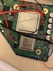
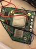
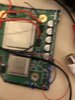
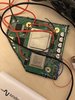
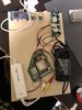
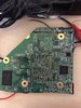
doing my first om6 trim and accidentally wired the voltages backwards, I.e. 5v to 1v, 3.3v to 1.5v, etc.
is my wii hosed?

If the answer is no, does anyone know how to fix this showing up on screen via composite

B3A2C0BF-F60B-4A27-93D0-D0813C1FBA33.jpeg
 
Wiis are pretty resilient, so it's probably fine. As for the video out problem, that's likely an issue with your U10 relocation.
 
Did you turn the power on while the voltage lines were wired incorrectly? If you did, throw it out. 5v down the 1v line is death, so is 3.3v down the 1.15v line. No fixing that. He's dead, Jim.
 
I reflowed the u10 wire, and nothing, I think my wii is cooked. I’m gonna try again with a second wii tomorrow
 
Update: I did it with a second wii and made sure the voltages were correct and I’m having the same problem. Totally new wii and everything. What should I try now
 
Are you certain that screen is working correctly?
 
Have you checked all the PTH outputs with a multimeter to ensure they're all outputting correctly?
 
Post more pictures of the board in question. Measure the voltages under load, so the voltages under load. Also, if I remember correctly, I'm not sure if the PTH regs have enough current rating to power the 1 and/or 1.15v rails. It's been years since I looked at 6 layer board stuff, but I think you should be using a PTR reg for those rails on a 6 layer board.
 
Post more pictures of the board in question. Measure the voltages under load, so the voltages under load. Also, if I remember correctly, I'm not sure if the PTH regs have enough current rating to power the 1 and/or 1.15v rails. It's been years since I looked at 6 layer board stuff, but I think you should be using a PTR reg for those rails on a 6 layer board.


Voltages are correct, even under load.

could this be a amp problem? I’m using a 45w dell laptop charger instead of batteries. Which should *in theory* be good but that might not be true in practice. How could I test this?

also here’s some pics
 

Attachments

  • B00EE362-FEC5-4A44-A240-9E2B5473E62C.jpeg
    B00EE362-FEC5-4A44-A240-9E2B5473E62C.jpeg
    2 MB · Views: 241
  • 1B7CB282-7DED-46C0-B2B9-B7B70C41CE8A.jpeg
    1B7CB282-7DED-46C0-B2B9-B7B70C41CE8A.jpeg
    1.8 MB · Views: 272
  • 4DFE7D93-E541-44CB-B5C7-5E64A8347F33.jpeg
    4DFE7D93-E541-44CB-B5C7-5E64A8347F33.jpeg
    1.7 MB · Views: 245
  • 1749D9BC-D243-47EB-8930-566F699E5139.jpeg
    1749D9BC-D243-47EB-8930-566F699E5139.jpeg
    1.6 MB · Views: 242
  • 806E443F-F40E-4B89-9307-F72A310D5910.jpeg
    806E443F-F40E-4B89-9307-F72A310D5910.jpeg
    1.4 MB · Views: 258
Voltages are correct, even under load.

could this be a amp problem? I’m using a 45w dell laptop charger instead of batteries. Which should *in theory* be good but that might not be true in practice. How could I test this?

also here’s some pics
You have to use batteries. The charging IC on the PMS can't output enough current to power the Wii without batteries attached.
 
Nono, you misunderstand me. I'm not using any standard PMS, simply Laptop Charger + PTH08080s.
Ah, my bad. That charger should be fine then. If you're getting all the right output voltages on the Wii, the next step would be measuring the U10 output. Also, please post a picture of the back of the board.
 
Ah, my bad. That charger should be fine then. If you're getting all the right output voltages on the Wii, the next step would be measuring the U10 output. Also, please post a picture of the back of the board.

sure, also I measured the u10 output and it's 3.1v
 

Attachments

  • F12D0683-6C13-4136-A5CD-E70C0D855AA2.jpeg
    F12D0683-6C13-4136-A5CD-E70C0D855AA2.jpeg
    2 MB · Views: 238
However, I just measured the u10 input, and it’s 0. That’s weird so I’ll try manually wiring it
 
3.1v going into u10, 3.1v exiting u10, ground cluster is continuous to ground
If it's 3.1v on the input, something is wrong. Did you sever the trace as recommend in the guide? The input of the u10 should be directly connected to the 3.3v rail. If your 3.3v rail is 3.1v, then your voltages aren't correct. Measure the voltages of each rail on the Wii motherboard itself.

Edit: also, it looks like you only have a single ground wire, and I can't tell how thick it is. Try running multiple ground wires, especially for high current stuff like the 6 layer boards.


It’s actually 3.16 out and 3.2 in, I think my PTHs are .1 off.


Also I’m using 22 gauge wire for gnd.

third, is there any way to verify the cut trace without desoldering the u10

fourth, I think I cut it properly since I did the u10 relocation before trimming and the board still booted.
 
Back
Top