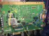
Worklog The Nintendo Swiitch - BocuD's first Wii portable

Ouch. I'd still try to fix the short and see if that revives it. You should probably get a better iron tip if that's what knocked them off. You should probably get one anyways, as a narrow tip will make soldering to the little things a LOT easier.
Yeah, will do :D
this iron seems like it's just too big. The other regulators are fine though... I'm just going to hope I can fix it. I can alway try to measure what the resistance is using the other regs and try to replace it, using normal resistors of course. I hope I can revive this one though since I have a LOT to do in order to finish the portable in time for the contest.
 
Well the short on that capacitor is between vin and ground, but those SMT parts would seem to be more important... Also, on all of my PTHs I have, that capacitor is not there :P
 
well I'll try to just remove the cap then, and TRY to replace the SMT resistors. I don't think I'll be able to resolveer SMT parts though so I'll probably just order a PowerMii Lite from @Noah
 
Okay, so i was trying to relocate the U10 and i think i really messed it up...
Anyone know how to fix it?
image.jpg

I destroyed the pad where i am supposed to add the wire and i also destroyed some other pad, but this is messed up in the guide as well so i dont think it is a problem. But that one pad... also, how can i remove the U10 without killing it?
 
Okay, so i was trying to relocate the U10 and i think i really messed it up...
Anyone know how to fix it?
View attachment 2751
I destroyed the pad where i am supposed to add the wire and i also destroyed some other pad, but this is messed up in the guide as well so i dont think it is a problem. But that one pad... also, how can i remove the U10 without killing it?
If you clean the area, you can find and scratch the trace that runs to the pad and solder a short wire from the U10 to that.

As for not destroying it, a good iron, some flux and a desoldering braid are handy. A good set of de-magged tweezers help too.
 
If you clean the area, you can find and scratch the trace that runs to the pad and solder a short wire from the U10 to that.

As for not destroying it, a good iron, some flux and a desoldering braid are handy. A good set of de-magged tweezers help too.
Okay, I'll try that after I get a new iron and will finish bluetooth first then.
 
I actually did the exact same thing on my board, the pad in the opposite corner of the wire pad isn't needed. As for the pad that would have the wire, I would suggest doing what I did, lift that pin on the u10 and solder to that. It seems there is something underneath there that makes it not work right...

As for removing the u10 I just cover it with solder until it just lifts off with the iron and then flick it on my desk :P The u10 can survive quite a bit of heat, I've never destroyed one doing it this way
 
w-what
How is that supposed to work
Also what soldering iron do you guys use? Mine seems to put me down every time.
 
w-what
How is that supposed to work
Also what soldering iron do you guys use? Mine seems to put me down every time.
You put a blob of solder on the 3 pins on the one side and a blob of solder on the 2 pins on the other. Then you heat both sides repeatedly while pushing with tweezers so the solder stays liquid and it can be easily removed. Here's a good and affordable soldering iron.
 
You put a blob of solder on the 3 pins on the one side and a blob of solder on the 2 pins on the other. Then you heat both sides repeatedly while pushing with tweezers so the solder stays liquid and it can be easily removed. Here's a good and affordable soldering iron.
Thanks, ill look into it. I'm currently using a digital one with thermometer and stuff but it has a really big tip. Can I also just replace the tip or do I actually need a new one? If i want to be able to solder wires to the nand for instance, will the iron you linked be sufficient?
 
Thanks, ill look into it. I'm currently using a digital one with thermometer and stuff but it has a really big tip. Can I also just replace the tip or do I actually need a new one? If i want to be able to solder wires to the nand for instance, will the iron you linked be sufficient?
Most irons have replaceable heads. Just get a pencil tip. It's pretty versatile for everything. You could get an even thinner tip for the NAND if you're worried about it but it should definitely be possible with a pencil tip.
 
Okay, I'll buy one of those then because my iron definitely has replaceable tips.
 
A larger tip would be fine, also you don't have to bother putting two blobs, I always just have one big blob that covers the whole chip :P

But if you iron has a replaceable tip, do that for sure, the ones with the temperature settings are almost always good
 
A larger tip would be fine, also you don't have to bother putting two blobs, I always just have one big blob that covers the whole chip :P

But if you iron has a replaceable tip, do that for sure, the ones with the temperature settings are almost always good
Okay, then I will do that. With this tip it was already hard to solder to the bluetooth tets pins, but I don't have any flux so maybe getting that will also help. Thanks!
 
Okay, I just removed all of the onboard regs and hooked my wii up to 3 bench power supplies. I don't know how its possible its working, but it is so im happy with it. I then trimmed my motherboard, and now I'll have to sand for an eternity. Whatever, everything for a working Wii portable. I also just ordered the L7009, and it will replace the 480x234 display I'm currently using. I also trimmed around 5mm around the red line to be safe.
IMG_5217.JPG

Pics of the trimmed motherboard:
IMG_5231.JPG

Does it look like I can get this motherboard working, after I solder the U10 on?
 

Attachments

  • IMG_5217.JPG
    IMG_5217.JPG
    2.1 MB · Views: 455
  • IMG_5225.JPG
    IMG_5225.JPG
    1.7 MB · Views: 434
Okay, I just removed all of the onboard regs and hooked my wii up to 3 bench power supplies. I don't know how its possible its working, but it is so im happy with it. I then trimmed my motherboard, and now I'll have to sand for an eternity. Whatever, everything for a working Wii portable. I also just ordered the L7009, and it will replace the 480x234 display I'm currently using. I also trimmed around 5mm around the red line to be safe.
View attachment 2805
Pics of the trimmed motherboard:
View attachment 2804
Does it look like I can get this motherboard working, after I solder the U10 on?
Definitely sand it good, especially the area above the NAND, you can see copper pieces on there.
 
Okay so after ~ 5 Wii motherboards (and fucking up everytime trying to solder a wire to the "U10 via") i just gave up on trimming a Wii. It is the most important part of my Portable so i had a question. Can a mod move this thread back to the Wii worklogs so I can finish this build later? When I get a new soldering iron and am able to have practiced some via wiring on old Wii motherboards, I might try to finish It and I really want to. For now I have another project that I want to submit and I hope you'll like that one. Its an Altoids Tin Pi Zero Portable NES Classic Mini clone based on a Raspberry Pi 2.
 
Back
Top