
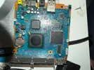
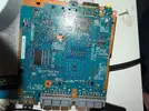
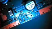
Could you send a pic of the motherboard top and bottom so we can see everything?
You are using an out of date browser. It may not display this or other websites correctly.
You should upgrade or use an alternative browser.
You should upgrade or use an alternative browser.
PS2 Ultra Slim
- Thread starter Wesk
- Start date
- Joined
- Apr 13, 2026
- Messages
- 11
- Likes
- 0
im not the best at taking pictures, hopefully these are clear enough.Could you send a pic of the motherboard top and bottom so we can see everything?
Attachments
Xtended
.
- Joined
- Apr 17, 2026
- Messages
- 1
- Likes
- 0
Just purchased a 79001 and submitted the case to pcbway. Just over 67.00USD to produce it the same as op. I will share the experience. Thanks for the mod op! Here from Macho Nacho channel, nice to meet everyone.
Edit: its been some time since I have last used PCBWAY, Donald Trump wanted a premium in tarrifs. I ended up finding a US based printing service provider on Craft Cloud. Print quantity of 4 gets them to around $100... Hoping for the a similar print quality, haven't hit buy yet, likely will. If ordered in a quantity of 1 the cost ends up at 137.80 delivered.
Edit: The SCPH-79001 arrived today, I managed to grab a fairly immaculate specimen. Got the console dissembled, and cleaned managed to tear the fan header from its contact pads while trying to unplug it, it broke off pretty clean, not real worried either way. The console itself came apart in what felt like 5mins, super elementary tear down.
Attachments
Last edited:
- Joined
- Apr 13, 2026
- Messages
- 11
- Likes
- 0
Unfortunately I was not able to figure out what happened to the original board I bought, but I will hold onto it to tinker with and see if I can get it working again, so I bought another board to continue the project and following the exact same process both times the second board has no issues and I was able to finish my first build.
Thanks for the project and for the help trying to fix the original board.
Thanks for the project and for the help trying to fix the original board.
Attachments
@Xtended
Not here — let’s keep it to mods and projects. "Donald Trump wanted a premium in tarrifs."I’ll probably be the one criticized for saying this (because its not anti-Trump), but the tariffs are not just “Trump wanted a premium.”
Here is my point:
The point is to make overseas manufacturing less of the automatic cheap option and give U.S.-based manufacturing and printing services a better chance to compete again. People can disagree with the method, and yes, it can raise costs short term, but the bigger goal is to bring manufacturing back here instead of depending on other countries for everything.
IMPORTANT TAKEAWAY - it worked!, because you did exactly what the tariffs are designed to encourage. You looked for a U.S.-based printing service.
I’ve been using SendCutSend for my builds they are US based, and I no longer use 3D print services if I dont have to because ive found other ways. I have even asked SendCutSend to get into 3D printing, but they are not interested right now.
I also use OSH Park, which is based in the U.S. Yes, they still send their boards overseas, but imagine if we keep supporting companies like that and they get enough support to eventually produce more here.
Think about it.
Anyway, I don’t want to derail the thread. Let’s get back to the build.
- Joined
- May 13, 2026
- Messages
- 6
- Likes
- 1
Hey there. I just started doing this mod but just now got to a problem. Firstly, i followed the Tutorial until i need to test my console and currently it does not turn on. When i wanted to check my solderjob (I rarely ever solder so i maybe did something wrong) the Pad for the Reset Switch got ripped off so now i have a plane PCB there. Is there any way to salvage that? Also i do have a 79003 so i needed another switch so i wanted to ask if there is a specific way i need to connect it?
Thats the switch i ordered: https://www.reichelt.de/de/de/shop/produkt/kurzhubtaster_6x6mm_hoehe_8_0mm_1_schliesser-375520
Update: Since i cannot connect the actual Power Button since it was connected to the now cut USB Power Outlet, i cannot even see if the playstation still works. Does anyone know what i need to do?
Last edited:
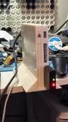
Check this out, maybe it will help answer some questions. The fan is useful to have connected, it will start on power up.Hey there. I just started doing this mod but just now got to a problem. Firstly, i followed the Tutorial until i need to test my console and currently it does not turn on. When i wanted to check my solderjob (I rarely ever solder so i maybe did something wrong) the Pad for the Reset Switch got ripped off so now i have a plane PCB there. Is there any way to salvage that? Also i do have a 79003 so i needed another switch so i wanted to ask if there is a specific way i need to connect it?
Thats the switch i ordered: https://www.reichelt.de/de/de/shop/produkt/kurzhubtaster_6x6mm_hoehe_8_0mm_1_schliesser-375520
Update: Since i cannot connect the actual Power Button since it was connected to the now cut USB Power Outlet, i cannot even see if the playstation still works. Does anyone know what i need to do?
Post again if you still need help.
I used an "L-shaped" piece of a project PCB board and fashioned it as shown below, with a PCB push button. You’ll need to shorten the plunger for your power button. I’ve done this on three of my builds, so I know the feeling when you pop open the shell and think, "uhh...", ha ha ha!!
If you're interested, I can get you the part numbers for the PCB, push button, and some more pics.
This stuff is so much fun!!!


who am I kidding.... I can't help myself I have to share all the info I have.
- Cut the PCB into a 5 via by 5 via square.
- Cut from the square a 2 via...
If you're interested, I can get you the part numbers for the PCB, push button, and some more pics.
This stuff is so much fun!!!
who am I kidding.... I can't help myself I have to share all the info I have.
- Cut the PCB into a 5 via by 5 via square.
- Cut from the square a 2 via...
Power / Reset Button
The mushy lid switch had to go and was replaced with a tactile push button. When using the lid switch, the unit would sometimes reset if you simply bumped the console — very annoying. This particular board still had the lid switch present, so I was able to simply remove it and replace it with a tactile push button.I found these push buttons on AliExpress and ordered a few different sizes. I sized it to be about the same height as the original lid switch off the motherboard. The size that worked out best was a copper SMD 4 × 4 × 3.5 mm...
- Joined
- May 13, 2026
- Messages
- 6
- Likes
- 1
Hey there. Thank you so much for the answer. Sadly i just realized that i probably miswrote what i meant (Sry i am not nativly speaking English) I meant the Pad where the Switch should connect to (the Yellow cable i marked here)Check this out, maybe it will help answer some questions. The fan is useful to have connected, it will start on power up.
Post again if you still need help.
I used an "L-shaped" piece of a project PCB board and fashioned it as shown below, with a PCB push button. You’ll need to shorten the plunger for your power button. I’ve done this on three of my builds, so I know the feeling when you pop open the shell and think, "uhh...", ha ha ha!!
If you're interested, I can get you the part numbers for the PCB, push button, and some more pics.
This stuff is so much fun!!!
who am I kidding.... I can't help myself I have to share all the info I have.
- Cut the PCB into a 5 via by 5 via square.
- Cut from the square a 2 via...
Power / Reset Button
The mushy lid switch had to go and was replaced with a tactile push button. When using the lid switch, the unit would sometimes reset if you simply bumped the console — very annoying. This particular board still had the lid switch present, so I was able to simply remove it and replace it with a tactile push button.

I found these push buttons on AliExpress and ordered a few different sizes. I sized it to be about the same height as the original lid switch off the motherboard. The size that worked out best was a copper SMD 4 × 4 × 3.5 mm...
The Switch itself is connected losely until i can mount it to the bottom of the case. I was able to scape off a bit ot the traces to connect the switch further down on the trace. But since these are so small they dont stay there and when i try to hotglue them in place the cable already came off. Currently its not holding whatsoever.
Sadly i dont have much experience with soldering. Is it still Salvageable?
Also if i misunderstood your answer im sorry. I just thought that my wording might have sent you down the wrong path.
If you need any more photos or infos, feel free to ask.
OK, let me take a closer look. You have some IPA to clean the flux off that spot adn maybe get some closer pics?Hey there. Thank you so much for the answer. Sadly i just realized that i probably miswrote what i meant (Sry i am not nativly speaking English) I meant the Pad where the Switch should connect to (the Yellow cable i marked here)
View attachment 42826
The Switch itself is connected losely until i can mount it to the bottom of the case. I was able to scape off a bit ot the traces to connect the switch further down on the trace. But since these are so small they dont stay there and when i try to hotglue them in place the cable already came off. Currently its not holding whatsoever.
View attachment 42827
Sadly i dont have much experience with soldering. Is it still Salvageable?
Also if i misunderstood your answer im sorry. I just thought that my wording might have sent you down the wrong path.
If you need any more photos or infos, feel free to ask.
- Joined
- May 13, 2026
- Messages
- 6
- Likes
- 1
Hey there. No problem. i cleaned it and took a new pic:OK, let me take a closer look. You have some IPA to clean the flux off that spot adn maybe get some closer pics?
If you need anything else, just tell me

- Joined
- May 13, 2026
- Messages
- 6
- Likes
- 1
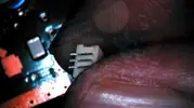
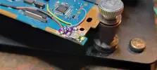
Thank you so much. I just tried soldering the switch to the new pad and turnes it on and the fan spun normally. It currently looks like that this trace here, is completely gone and not connected correctly (my Photos are not good enough to correctly show it i think, but via eyeview i´d say the trace is disconnected):
Here is my Photo i took via camera (Sadly i dont have the correct equipment to take such detailed photos, i veen turned on the light so the copper would shine more)
There the copper line is complety ripped out and does not make a connection. Do i need to connect that trace again? Or is that trace irrelevant/does not need to be connected perhaps? (I definetly think that doesnt happen often or ever in circuitry.)
@ImCriptix
That chip is the Mechacon, if that trace is tied back to the Optical drive then maybe not. I would have to investigate that further. If the board powers on and ou have a dsplay. See if you can drop in a FMCB and MX4SIO and try to see if a game loads. Or repair the trace.
That chip is the Mechacon, if that trace is tied back to the Optical drive then maybe not. I would have to investigate that further. If the board powers on and ou have a dsplay. See if you can drop in a FMCB and MX4SIO and try to see if a game loads. Or repair the trace.
- Joined
- May 13, 2026
- Messages
- 6
- Likes
- 1
@FatBaldDad
Conmsole turns on, start, outputs video and i can start OPL and load games. Playing the game was also possible.
Conmsole turns on, start, outputs video and i can start OPL and load games. Playing the game was also possible.
Very interesting. When I get some time Ill look into it some more just out of curiousity. Have fun!@FatBaldDad
Conmsole turns on, start, outputs video and i can start OPL and load games. Playing the game was also possible.
- Joined
- May 13, 2026
- Messages
- 6
- Likes
- 1
Thank you so much for the helpVery interesting. When I get some time Ill look into it some more just out of curiousity. Have fun!
Densarc
.
- Joined
- Jun 1, 2026
- Messages
- 2
- Likes
- 1
Almost done.
1 Board is cut and powers on
2 HDMI Electron shepard done and working
3 The internal sd card mod
I tried it 3 times and is does not read the sdcard in opl or launcher, also evertime i cut the sd adapter it wont read in a pc either so i think its time to move on to using Gen2 MMCE in memory slot 1
I have the the gen2 with display as mention in earlier posts. The problem is it does not boot to FMCB at all with the supplied card is it supposed to or do i need seperate FMCB card? Seems like i should only need 1
BITFUNX PSxMemCard Gen2 the same thing as ps2sdx and if so can i just add a 256GB blank card and build it from zero
If the bolded text is correct is there a good setup tutorial aroundUse https://ps2homebrewstore.com/
Setup your card following the instructions there.
Yes, you can use a 256Gb mSD card. Would be best if its an A2. The cards that ship with the PSXMCG2 are good for just game saves but for exploit, game storage and game saves you do need a better card.
Setup your card following the instructions there.
Yes, you can use a 256Gb mSD card. Would be best if its an A2. The cards that ship with the PSXMCG2 are good for just game saves but for exploit, game storage and game saves you do need a better card.
Last edited:
Similar threads
- Replies
- 8
- Views
- 10K