Worklog Toshiiba

Joined
Nov 8, 2018
Messages
2
Likes
0
Ah that makes sense. I guess I'll just make do with more juice. Thanks!
Good luck with the project :)
 

vikMKW

.
Joined
Apr 23, 2019
Messages
49
Likes
56
Location
Ventura, California
First, congrats to everyone that completed their projects. All of the entries are absolutely superb, and some of straight up production value. What a fun contest to be following!

I took some time off, but abandonment was never an option. Completing the project by the deadline was a reach goal, which I then knew would not happen after tripping over myself with the video problem. Speaking of the lack of video out, don't desolder DA1, DA2, DA4. Despite the traces that leave the ICs being severed, that's not enough reason to desolder a component. Young player's trap.
2020-08-24_18h54_21.png
The wii then booted, but intermittently. This was not too surprising, as I tried to get away with a wire gauge that was just shy of the required spec for the power rails. I've got a bin of mystery wire, so I calculate the wire gauge by measuring the strands. Highly recommend doing this for anyone that's not sure if your wire can carry enough current. I beefed up the wires and solved this problem instantly, which felt nice compared to the prior issue.
2020-08-24_19h00_30.png

Shout out to @mokus for providing clear, documented empirical measurements for each rail (with & w/o components). It's been a valuable dataset.

One GC via solder reflow later, and my controllers worked! It's a bit tricky to see the GC controller connections, but I'm pleased with how clean it turned out. A line of B-7000 adhesive holds down the 33AWG magnet wire. It's the same adhesive used to attach smartphone screens to the phone chassis... ask me how I know :blush: .
20200824_191354.jpg


We have gameplay!
20200824_181545.jpg

Next step is to design a PCB for a VGA connector and an audio jack that will mount in place of the multi-out connector. It's a matter of placement optimization and getting the dimensions correct. I made a KiCAD footprint for the multi-out holes.
2020-08-24_19h22_45.png
2020-08-24_19h23_04.png

The plan is to shorten a VGA cable and reterminate one end with a DB-15 connector for video. Audio will be carried with a standard aux cord. Perhaps the build can be completed before 2020 comes to an end?
 

vikMKW

.
Joined
Apr 23, 2019
Messages
49
Likes
56
Location
Ventura, California
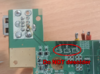
And we have video! The VGA output looks superb...though we don't have audio :blush:
20200919_102839.jpg
Pads on the bottom side of the PCB are connected to the wii multi-out connector's through holes. It's a blind solder joint, as I had to push a fine tip iron through the holes and have the solder wick through to the pads. It worked phenomenally, without the need to reflow joints.
2020-09-19_12h03_47.png

20200919_100309.jpg
20200919_100334.jpg
My dimensions were slightly off, because my paper PCBs were incorrectly sized due to my default page setup on KiCAD not being set to 8.5x11" paper. Luckily I was able to shorten the top edge with a file. Additionally, I added a cutout in front of the headphone jack. Unsure why I didn't position it further forward. Otherwise, no components interfered.
20200917_205157.jpg
20200919_121532.jpg


Anyone see what mistake I could've made with the audio?

I'm now working on a charge board using a BQ24133 & BQ76925. Currently digesting the datasheets and user guides front to back. I've also started to work on a replacement sensor bar using SMD LEDs. As soon as I build it and confirm it works, I can start figuring out how I should bend some sheet metal around the LCD.
---------------------------------------------------------------------------------------------------------------------------------------------------------------------------------------------------------------------------
EDIT 9/19/2020
Perhaps this is not the solution, but I got some audio out. I noticed U7 has no power. The compendium tells me that's 12V. I severed its connection to the 12V power plane and connected 5V to U7's VCC pin. I got some massive static, but was able to make out the Melee background music. Moving the cable any amount unpredictably influences the sound.
20200919_171540.jpg

Is the solution to pull Audio L and Audio R directly from the AVE (pin 39, pin 43 respectively?)
---------------------------------------------------------------------------------------------------------------------------------------------------------------------------------------------------------------------------
EDIT 9/21/2020
Yes, audio must be pulled directly from the AVE or at least before the U7. To keep it clean, I removed U7 and bridged the corresponding signals.
Screenshot_39.png
The definitive trim guide has some young player's traps. The signal before U7 and after U7 are technically different signals as they're passed through the IC. The guide mentions that there "are multiple alternate points to connect audio and video to," while representing them with colors and numbers, but that does not mean its the same continuous signal.
2020-09-21_22h30_53.png
Tl dr; connect audio at the AVE.
 
Last edited:
Top