What's up, figured I'd start a worklog for this project. It's probably going to be a long term project but I had some questions so I guess it makes sense to put them in a worklog. Feel free to move this post around somewhere if it's better suited elsewhere.
I've made several Pi portables in the past but want to try my hand at something more challenging.
I have purchased / acquired most of the components already, expect for a screen (going to use a composite screen for now to keep the build simple and less expensive).
RVL-PSU
GC+ 2.0
PAM8803 audio amp
2S 18650 charging board
etc.
I have access to some good 3D printers and I plan to use the GWii case, but Wesk's version so that I can match the bezel to whatever composite display I end up buying.
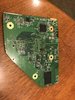
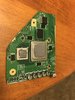
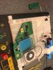
I trimmed my Wii (4-layer), did the U10 relocation, and wired up the 3.3V, 1.15V, and 1V, and composite video, but am having some issues.
I think the main issue is that I'm only getting about 0.8V on the 1V rail. Even with no load the RVL-PSU seems to only put out .9V on the 1V output, is this an issue?
At first I thought some of voltage rails were shorted but looking through the forums the resistances between some of the rails are okay to be pretty low? Right now I am reading >1k ohms between 3.3V and ground, only 28.5 ohms between 1.15V and ground, and 188 ohms between 1V and ground. Maybe I need to sand down the edges more?
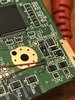
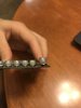
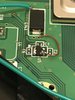
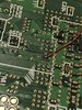
It's also possible I'm having a U10 issue. When I first relocated it before trimming I tested it out and the Wii booted up without issue, but when I tried turning it off the power button didn't turn the console off and I had to pull the plug. Then I tried turning the console back on and it didn't respond... But being impatient I decided to proceed with the trim. I cut the trace as shown in the picture but I also have just bent up that pin so that it is only connected to the wire to the GPU pin and not the board itself (pictured). Is this an issue? Also, maybe when cutting the trace I shorted the two internal layers by cutting too deep with a box cutter? Not sure if this is a thing. I did check the pins as per the BB guide to troubleshooting U10 but everything seemed to check out.
Also worth noting that when I was sanding down the board I lowkey ripped off the C134 cap, but I did solder it back in place in the correct orientation.
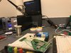
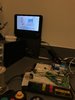
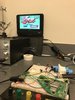
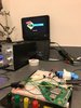
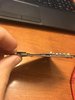
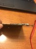
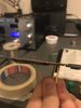
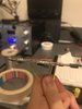
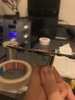
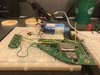
If anyone has any advice it would be greatly appreciated. I have two more Wii's to work with (guy on Facebook just sold me two Wii's with faulty disk drives for 20 bucks) so if I have to start over it's not the end of the world. Photos attached; it is a bit rough in the photos but this was after several iterations of troubleshooting and at that point I didn't care if it looked nice, just wanted it to work.
Thanks! And sorry for the novel. Looking forward to the rest of this build.
I've made several Pi portables in the past but want to try my hand at something more challenging.
I have purchased / acquired most of the components already, expect for a screen (going to use a composite screen for now to keep the build simple and less expensive).
RVL-PSU
GC+ 2.0
PAM8803 audio amp
2S 18650 charging board
etc.
I have access to some good 3D printers and I plan to use the GWii case, but Wesk's version so that I can match the bezel to whatever composite display I end up buying.
I trimmed my Wii (4-layer), did the U10 relocation, and wired up the 3.3V, 1.15V, and 1V, and composite video, but am having some issues.
I think the main issue is that I'm only getting about 0.8V on the 1V rail. Even with no load the RVL-PSU seems to only put out .9V on the 1V output, is this an issue?
At first I thought some of voltage rails were shorted but looking through the forums the resistances between some of the rails are okay to be pretty low? Right now I am reading >1k ohms between 3.3V and ground, only 28.5 ohms between 1.15V and ground, and 188 ohms between 1V and ground. Maybe I need to sand down the edges more?
It's also possible I'm having a U10 issue. When I first relocated it before trimming I tested it out and the Wii booted up without issue, but when I tried turning it off the power button didn't turn the console off and I had to pull the plug. Then I tried turning the console back on and it didn't respond... But being impatient I decided to proceed with the trim. I cut the trace as shown in the picture but I also have just bent up that pin so that it is only connected to the wire to the GPU pin and not the board itself (pictured). Is this an issue? Also, maybe when cutting the trace I shorted the two internal layers by cutting too deep with a box cutter? Not sure if this is a thing. I did check the pins as per the BB guide to troubleshooting U10 but everything seemed to check out.
Also worth noting that when I was sanding down the board I lowkey ripped off the C134 cap, but I did solder it back in place in the correct orientation.
If anyone has any advice it would be greatly appreciated. I have two more Wii's to work with (guy on Facebook just sold me two Wii's with faulty disk drives for 20 bucks) so if I have to start over it's not the end of the world. Photos attached; it is a bit rough in the photos but this was after several iterations of troubleshooting and at that point I didn't care if it looked nice, just wanted it to work.
Thanks! And sorry for the novel. Looking forward to the rest of this build.
Attachments
-
 709 KB Views: 424
 -
 1.8 MB Views: 425
 -
 1 MB Views: 418