Worklog Madmorda's First Wii Portable (Wii S Lite)

Madmorda

Painting Queen
.
.
Joined
Oct 27, 2016
Messages
725
Likes
1,718
Location
Texas
Portables
2
Yeah, carve it. I just like using power tools >.>. I'd say that one is designed to sit on top of either the chipset itself, or an adhesive copper plate alongside a finned sink.
If it were a bit thicker, it'd be doable. The base is only 1mm thick though, so I wouldn't risk it :P. If you get one and do it though, be sure and let me know how it turns out :) so far I'm loving the fan, but there's always room for improvement
 

Stitches

2 and a Half Dollarydoos
Staff member
.
.
Joined
Feb 5, 2017
Messages
3,817
Likes
3,011
Location
Banana Bender Land, Australia
Portables
6
Sure! I do plan at some point in the future to put a Wii inside an old Leapster shell and that fan would fit almost perfectly inside the battery window form in the bottom. Looking at Gman's sink setups it would probably be okay on its own, but I'd put a plate and a bit of fin anyway just to be safe.
 

Madmorda

Painting Queen
.
.
Joined
Oct 27, 2016
Messages
725
Likes
1,718
Location
Texas
Portables
2
How's the case work coming along?
20170306_135942.jpg 20170306_135949.jpg 20170306_135957.jpg
I am still planning on using the ds lite looking case, but since it is so small, I'm also looking at other options as well. I found this case that I actually like quite a bit. It's not too fat, and has plenty of room for a wiip. Too small for a 7" screen though so it likely won't be used. I'm going back and forth on my screen for the wiip (which is what will determine the case). On one hand, I really want component. On the other hand, the screens that support it are larger, and I wanted a smaller portable this time around. I think I'll stick with composite, but it really seems like a shame. Unless someone knows of a 4-5" screen that takes component and has a small circuit board? I finally got some monies, so I can get this train moving again, but I still have to order a screen.
 

pipbug

.
Joined
Feb 17, 2017
Messages
93
Likes
95
Location
British Columbia, Canada
View attachment 1674 View attachment 1675 View attachment 1676
I am still planning on using the ds lite looking case, but since it is so small, I'm also looking at other options as well. I found this case that I actually like quite a bit. It's not too fat, and has plenty of room for a wiip. Too small for a 7" screen though so it likely won't be used. I'm going back and forth on my screen for the wiip (which is what will determine the case). On one hand, I really want component. On the other hand, the screens that support it are larger, and I wanted a smaller portable this time around. I think I'll stick with composite, but it really seems like a shame. Unless someone knows of a 4-5" screen that takes component and has a small circuit board? I finally got some monies, so I can get this train moving again, but I still have to order a screen.
Right on! Personally I just use composite on screens that are less than 6" as the resolution is pretty low anyways. No matter which path you take I'm sure it'll turn out great!
 

Madmorda

Painting Queen
.
.
Joined
Oct 27, 2016
Messages
725
Likes
1,718
Location
Texas
Portables
2
Okay so I'm totally ready to jump back into this. I finally have the cash to buy the things I need, so this will be fun :D. Small progress today, mostly working out my design, but enough to be worth updating here.

First of all, I haven't updated this here I don't think, but I've trimmed two wiis so far. Unfortunately, neither of them work. One of them had something mysterious making it not work, and I managed to make a mess of it while troubleshooting. The second one I did really neatly, but it has 2/3 voltage lines shorted to ground. No amount of sanding seems to fix it, so I'm just moving on to wii #3. Third time's the charm. Hopefully I'll get that trim done this week, but if not, my 8 week class is about to end so I'll have more project time starting next week

20170306_202136.jpg 20170308_081214.jpg
On the left here you can see the old plastic thing that holds the buttons etc. I have decided on a different layout for the internals, so I have revised this. Also my fingers weren't long enough to move the c-stick comfortably haha. I am tentatively naming this the Wii S Lite, because it will look like a ds lite when done. If for some reason it won't fit in this case, it will be renamed. I have printed it out. I have no idea how, but I got the measurements for the d-pad horribly wrong so I need to fix that. Also the word Lite didn't come out well so I will either scale the logo up or remove it altogether.

*Note that there's no start button hole. I am thinking I'll make it like the z button, but on the opposite side.

20170306_202838.jpg
On to the new layout! I can fit at least two 18650s in if I put them end to end with the wii oriented like this. They fit just about perfectly. I couldn't do this before because of the sliders, but I'm relocating those.

20170306_202923.jpg 20170306_202943.jpg
I'm loving this fan btw. Okay so the wii will be face up, with a 7ish-mm heatsink on top of it. This fan sucks in the circular hole and blows out the rectangular joke in the side. It will go face down on top of said heatsink with the rectangular side venting hot air out the back of the ds. It's kind of perfect too because it will look like there's a ds cart slot right where there should be one. I'm kinda hoping I'll be able to fit some very thin speakers in the top part along with the screen.
 
Last edited:

Stitches

2 and a Half Dollarydoos
Staff member
.
.
Joined
Feb 5, 2017
Messages
3,817
Likes
3,011
Location
Banana Bender Land, Australia
Portables
6
View attachment 1674 View attachment 1675 View attachment 1676
I am still planning on using the ds lite looking case, but since it is so small, I'm also looking at other options as well. I found this case that I actually like quite a bit. It's not too fat, and has plenty of room for a wiip. Too small for a 7" screen though so it likely won't be used. I'm going back and forth on my screen for the wiip (which is what will determine the case). On one hand, I really want component. On the other hand, the screens that support it are larger, and I wanted a smaller portable this time around. I think I'll stick with composite, but it really seems like a shame. Unless someone knows of a 4-5" screen that takes component and has a small circuit board? I finally got some monies, so I can get this train moving again, but I still have to order a screen.
This screen is 5 inches, 16:9 at 800x480. It uses this driver board and accepts component in without any modifications. Very good voltage range too. A 7.4v pack would be sufficient.
 

Madmorda

Painting Queen
.
.
Joined
Oct 27, 2016
Messages
725
Likes
1,718
Location
Texas
Portables
2
This screen is 5 inches, 16:9 at 800x480. It uses this driver board and accepts component in without any modifications. Very good voltage range too. A 7.4v pack would be sufficient.
Thanks for finding this! My battery pack is 5v, and it says it should work on 5v. You think it'd be okay? I've had a couple instances where manufacturers were a little optimistic (like with my fan). Thanks so much for finding this! :)
 

Aurelio

ᕕ( ᐛ )ᕗ
Staff member
.
.
.
.
.
Joined
Mar 3, 2016
Messages
2,228
Likes
2,952
Portables
2
Thanks for finding this! I'll keep it in mind. Unfortunately, my battery pack is 5v. If I change battery packs though I'll definitely give this a try! :D
That driver board has a first stage of regulation with a step down from the 12V input (or whatever). Usually it's regulated down to 5V or 3.3V. You can remove that regulator on connect directly 5V (or 3.3V depending on what it uses). I did this on my portable and it works perfectly :)
 

Madmorda

Painting Queen
.
.
Joined
Oct 27, 2016
Messages
725
Likes
1,718
Location
Texas
Portables
2
That driver board has a first stage of regulation with a step down from the 12V input (or whatever). Usually it's regulated down to 5V or 3.3V. You can remove that regulator on connect directly 5V (or 3.3V depending on what it uses). I did this on my portable and it works perfectly :)
Thanks! You guys rock. I'll order those parts pronto :D. I looked everywhere (well apparently not everywhere) and couldn't find a screen of that size with component.
 

Stitches

2 and a Half Dollarydoos
Staff member
.
.
Joined
Feb 5, 2017
Messages
3,817
Likes
3,011
Location
Banana Bender Land, Australia
Portables
6
The screen itself is about 120mm x 76mm, for size reference.
 

Stitches

2 and a Half Dollarydoos
Staff member
.
.
Joined
Feb 5, 2017
Messages
3,817
Likes
3,011
Location
Banana Bender Land, Australia
Portables
6
If you have one with you, how thick is it? And the driver board if possible
Thickness is 3.1-3.2mm. The DV board I don't know the dimensions of. The website doesn't have a datasheet for it and mine hasn't arrived yet, but I'm fairly certain it's smaller than the screen.
 

Madmorda

Painting Queen
.
.
Joined
Oct 27, 2016
Messages
725
Likes
1,718
Location
Texas
Portables
2
Thank you :). I checked the driver board again and this time saw that the dimensions actually are there, although I didn't see them last time.

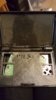
Here's where I'm at space-wise. I'm mostly documenting this for myself to refer back to, so apologies for the kinda-unnecessary update.

The screen will fit the top half much nicer than the 4.3", so with the added video quality, I am really hoping to get this working. Unfortunately, that leaves me in an awkward spot as far as speaker location, but it's worth it
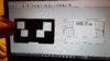
 :P

Length and Width:
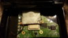
Screen: 120x76mm by Stitches' dimensions.
Case: 135x80mm, not including the rounded out edges.
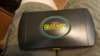
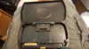
Driver: 83x58mm. The screen will have to sit on top of 28mm of it
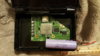
Depth:
Case: 9mm
Screen: 3.2mm
Screen holder: 0.8mm (this will be 3d printed so there is some wiggle room. Assuming it adds 0.8 for simplicity)
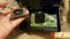
Driver: 5mm at the part the screen must lie on, based on the picture. 8mm at the thickest part.

That's pretty exact. These measurements are probably a tiny bit off, but it should just barely all fit. If it doesn't, I can remove the inductor on the driver board like Luke did for his 3dsPi project and then it will fit for sure.

As far as audio goes, it might still be easier to put the speakers in the top half, because I want them facing the player, not off to the side. I have about 7.5mm per side for speaker holes. I was thinking that if I used flat speakers (5mm or less), I could lay them partially under the screen. I have some 40x5mm speakers that I tested using the world's worst audio amplifier board, and they seem to be of pretty good quality. I will compare those with some other speakers when I have a real amplifier board. Any suggestions are welcome :)

Last thing: If somebody has the time, I could really use some help figuring out what I need to get my headphone jack up and running because I see a lot of conflicting information. The one in my GCP is wired up to the audio amplifier and can break your eardrums if you don't turn it down, and I want to fix that in my wiip.
https://bitbuilt.net/forums/index.php?threads/how-to-wire-a-stereo-headphone-jack.978/#post-10442
I read this through a couple times. Wiring up the switching headphone jack directly to the wii means that the volume on the amplifier wouldn't control it in the heaphones. Looking at the datasheet for the TPA6021A4, and with all of the resistors and caps (I count 11 caps and 4 resistors) it looks like it would be a huge mess inside so I don't think that's what you guys have been using. I've been trying to find an amplifier that has a headphone jack for audio out, pins for speaker out, and volume control built in but it's proving difficult. If someone could point me to the obvious, that would be amazing :)
 

Stitches

2 and a Half Dollarydoos
Staff member
.
.
Joined
Feb 5, 2017
Messages
3,817
Likes
3,011
Location
Banana Bender Land, Australia
Portables
6
Wow how did I miss that.... I must not have read the last line.
 

GC64

.
Joined
Jul 3, 2016
Messages
177
Likes
153
Location
Georgia
Portables
2
Have you already considered the PAM8803 Amp from the Portablizing BOM? It has volume control and an output for speakers like most amps. Here's the wiring diagram I used for wiring a headphone jack, it should work the same on the amp:
View attachment 1372

By default, your internal speakers will be on, but when you insert a cable into the jack, the switch is made mechanically to route the audio to your headphones instead of your internal speakers.
 

Luke

.
Joined
May 23, 2016
Messages
209
Likes
221
Location
Texas
Portables
2
Well, I feel obligated to say that as Aurelio pointed out in another thread (the one that Madmorda mentioned in her post), the diagram I made is "not the proper way" because it doesn't in any way switch the amp to "headphone level volume" which could result in blowing out your headphones. The guy that I made the diagram for (was it you GC64?) was asking about the exact amp that I used in my diagram, and for that amp there really is no other way.

This is how I've wired my jacks in the past and how I learned to do it from elsewhere and I haven't had any problems, and well I don't know if others besides me do it this way, but use it at your own risk.

I too would be quite interested to know what other people use if they don't go so far as to wire up an amp chip with all those resistors and caps themselves.
 
Last edited:

GC64

.
Joined
Jul 3, 2016
Messages
177
Likes
153
Location
Georgia
Portables
2
Well, I feel obligated to say that as Aurelio pointed out in another thread (the one that Madmorda mentioned in her post), the diagram I made is "not the proper way" because it doesn't in any way switch the amp to "headphone level volume" which could result in blowing out your headphones. The guy that I made the diagram for (was it you GC64?) was asking about the exact amp that I used in my diagram, and for that amp there really is no other way.

This is how I've wired my jacks in the past and how I learned to do it from elsewhere and I haven't had any problems, and well I don't know if others besides me do it this way, but use it at your own risk.

I too would be quite interested to know what other people use if they don't go so far as to wire up an amp chip with all those resistors and caps themselves.
Yeah, I was the one you showed how to wire it. I figured if everyone uses the amp in the portablizing BOM then if any, that should be the one the diagram works for. Though I would like to know the most common method people use for wiring up a headphone jack since most people seem to have no problems with it.
 

Madmorda

Painting Queen
.
.
Joined
Oct 27, 2016
Messages
725
Likes
1,718
Location
Texas
Portables
2
The one in my GCP is wired up to the audio amplifier and can break your eardrums if you don't turn it down
it doesn't in any way switch the amp to "headphone level volume" which could result in blowing out your headphones.
Yeah that's my problem. I was planning on using the one in the bom, but there has to be a better way. When I was putting the switching jack in the gcp, I connected L, R, and ground. I put a resistor between the ground pin on the jack and the ground it was connected to, expecting that it would lower the volume. But connecting it to ground at all caused terrible audio, and I went all the way up to 10k ohms and it made no difference in volume. So my jack isn't connected to ground at all, just left and right audio.

When @Aurelio said that you needed 2 amplifiers, maybe he meant that you connect one amp to the board, then instead of wiring it to speakers, wire it to the jack. Then on the other part of the jack, wire that to the LR on the second amp. Then that amp would be connected to the speakers. Would that work? I still see the problem of volume control, but maybe the first amp would control it in the speakers as well?
 

Aurelio

ᕕ( ᐛ )ᕗ
Staff member
.
.
.
.
.
Joined
Mar 3, 2016
Messages
2,228
Likes
2,952
Portables
2
When @Aurelio said that you needed 2 amplifiers, maybe he meant that you connect one amp to the board, then instead of wiring it to speakers, wire it to the jack. Then on the other part of the jack, wire that to the LR on the second amp. Then that amp would be connected to the speakers. Would that work? I still see the problem of volume control, but maybe the first amp would control it in the speakers as well?
Nope, not really what I meant. The best way is to use amplifier ICs that have both amplifiers (class D for speakers and class G for headphones) and that can handle automatically the headphones/speakers switching.
This is going to come out soon hopefully and will handle everything :)
 
Top