imerani
.
- Joined
- Dec 10, 2024
- Messages
- 4
- Likes
- 3
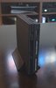
Yeah resin is a bit fragile, no way around that sadly. I like the two tone appearance that the pale ports provide. Very nice build!This is how it looks printed in black resin, from PCBWay. Not bad, the only problem is it feels fragile, like it can break if falls. The original PS2 was silver satin, so that's why the color of the controller ports.
Hi!
All my PS2s are also chipped.
This one is using Modbo 5.0 (but same issue using FMCB)
OPL 1.2 for MX4IO support
Ack and Ground is bridged.
The issue may be that I didn't use the resistance?
I read all sorts of conflicting guides saying that it is not necessary, but then why include it in the first place?
I think I initially followed Macho Nacho's video, but then I noticed that when he installed the ElectronAnalog HDMI mod, he didn't shield the component wires to ground which IMO isn't great advice as that will introduce interference (I tried without shielding and it was night and day).
So I am wondering if his advice to skip the resistance is also as misguided? In reality, what is the purpose of that resistance?
Q
It depends what look you are after, and how much money you have, if you care to elaborate on those points a little bit?
As for the files to print, I agree the initial post is a little bit confusing as it links to an updated version that does not include the additional button and SD card bracket. I myself have got caught out as well and placed an initial order that had to be replaced as I realised the additional parts to be printed are in the actual original download.
Q
I've attached pictures of my latest build to give you an idea.
The material is is:
HP MJF Nylon PA12
The color is:
Dyed black
The texture and finish is:
Shot peened
I used a website called CraftCloud that guides you through the whole process and makes it easy for you, then gives you a selection of 3D printer vendors to chose from depending of what you selected, your location etc etc, give it a try and it will show you what the finishes and materials look like.
If you want transparent, the PCBway transparent resin is the answer, but be prepared to pay extra.
Q
I also had noise AnalogElectron.
I fixed it in 2 steps.
Step one, shield the cables, AnalogElectron even has the ground via holes for this.
Step two, routing was really important for me.
I isolated main ground and 5 volt (or is it 3.3) and ran them down under the motherboard to come out the other side.
The shielded video wires run on the top side of the motherboard right above the main shield plate, this way I avoid interference with 5 volt and all the other components from the motherboard
Same for audio wire, except I ran them a bit further down.
The video, audio, and power wires never intersect.
This has reduced the noise to very closely match my other PS2 that uses component+RetroTink 4K, where before it uses to be very noticeable and distracting.
Hope this helps.
Q
Just a note, maybe this was trimmed after the fact so ignore me if so, but you dont need to hookup the whole right row of that modbo except CX. SX is for PS1 and Y to A is for DVD, which obviously, we don't need anymore. This will save you lots of time on your next build as those B/G/H/I on this model aren't exactly fun soldering jobs
@DoeKe
Now it's making sense as to what was going on. Ha! I think you've got it now. Another thing to note is that the MX4SIO doesn't always show up right away on that version of OPL because the default is USB. You have to use the D-pad to select the next location.
Format your microSD card as exFAT and put your games in a folder named "DVD" in the root directory. Also, a handy tool is "OPL Manager" to get all the artwork, saves, cheats, etc., set up. You probably already know this.
@PurpleSkyz
Just something else to consider if the microSD card isn't showing up without taking it out and putting it back in: it could be due to using that version of OPL. It typically defaults to USB, and you have to press right or left on the D-pad to select the MX4SIO. I know that in launchELF, you have to select "mass0" to open that file location, and then when you back out, "MX4SIO" shows up in the file tree. Maybe you already know this, but I'm just throwing out ideas to help.
What cards did you try, which failed. I have only been using the Samsung cards that Tito recomends.
Thanks for your help!
I modified a v1.2 case to accomodate a PD trigger board to use instead of a regular DC jack. @Wesk might want to add this somewere in one of his posts
This is for a HW-398 trigger board.
View attachment 33851
Make sure your trigger/decoy board is set to 9V
There are no guarantees that powering your console this way will not fry it. PS2 79XXX is rated for 8.5V input so do this at your own risk.
The print for me was a snug fit and I think you can just push the board in without a retainer but you risk displacing it. You need to push the buisiness end into the hole first and then push the rest of the board flat onto the platform.
You will need to use 2 M3x6 screws to mount a retainer. The screw holes are small enough for the screws to self tap. Make sure to not overtighten them else the standoffs will break off.
I am including a test part so you do not need to print the whole half to test fit your board.
CAD files are included so you can modify the design if necessary. The TestPart.step is also included and can be used to modify the other variations of the top shell.
Hi! I've got question regarding the usage of HW-398 trigger board - does it support modern PPS standard chargers which provide 3.7-11v at 5Ampers? Some GaN chargers have support for such standard at theoretically can be use to make 9V/5A output for PS2.
You missed the point of my question. These specific chargers that you sent work, sure but they can't provide 5A at 9V through PPS... Advertisment of HW-398 have usually written that they support PPS handshake and some people have issues with it. PPS is the only way that you can have 5A at 9V. For example this one from Anker have compatibility with PPS and can provide range (PPS): 4.5V-20V, 5A (100W Max). This is really cool but like I said some people say that HW-398 board cant communicate using PPS and just use 9V 3A from PD 3.0...I've found that they do require a specific type of charger. Either a fast charger or super fast charger, as some cheap chargers, or ones that just provide basic charge don't seem to work.
I have these specific chargers, and can confirm that they work very well:
- UGREEN 65W USB C Charger Block, Nexode 4-Port
- SAMSUNG 50W Duo Power Adapter Wall Charger, 2 Ports
- Samsung 25W Wall Charger Power Adapter
I would assume any GaN charger, Fast, or Super Fast Charger for phones would work just as well.
I just tend to buy multi-port ones to use on multiple consoles at once.
However, something like this should work, too:
UGREEN 30W USB C Charger, Nexode Foldable GaN PPS Compact Fast Wall Charger Block
i am new nice to meet you allhey so i have one of those boards that does not have a power switch ive followed titos build do far but i dont know where to cut the trace and i am also not getting power

Do you mean the lid switch? When there is no lid switch you can skip that step (cutting the trace).hey so i have one of those boards that does not have a power switch ive followed titos build do far but i dont know where to cut the trace and i am also not getting power
I see the problem here: you have the reset pad soldered to ground. It should be connected to the N.O. (normally open) contact on your push button. When you press the button, the reset pad should make contact with ground. Additionally, you have both contacts of the push button tied to ground. One side of the push button should go to ground, and the other should go to the reset pad.Here's the pictures of my build so far