- Joined
- Jun 28, 2017
- Messages
- 70
- Likes
- 114
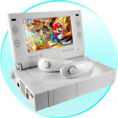
Hey everybody, I am working on my first Wii portable. Because I am not too familiar with casework or 3D printing, I was hoping to start easy and create it in the laptop style sort of similar to this picture.
So far I already have my portablizemii installed on the wii and my custom regulators wired up and putting out the proper voltages (I will add those pictures soon)
As of right now I am stuck a little. Since I will not be trimming my wii motherboard, I was looking around the forum to see how I could go about connecting the custom regulators with an untrimmed board. I stumbled on the below thread and found some helpful comments
https://bitbuilt.net/forums/index.p...e-main-regulators-on-the-board.700/#post-7118
In the thread above, Gman said this:
"Remove the large inductors and capacitors that are located outside of the OMGWTF trim. Also most importantly remove U18 and the 3.3v standby regulator. On the back, remove U15, U16, and U17. I usually just pull everything off with pliers and then use a soldering iron to clean up the connections so nothing has shorted. Some boards you can get away with just removing U18, but others I have found it won't work so to be sure, you could just remove everything."
and then Shank said:
"You will also need to connect both the 3.3v and 3.3v standby lines together and power them off of the 3.3v line.
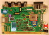
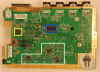
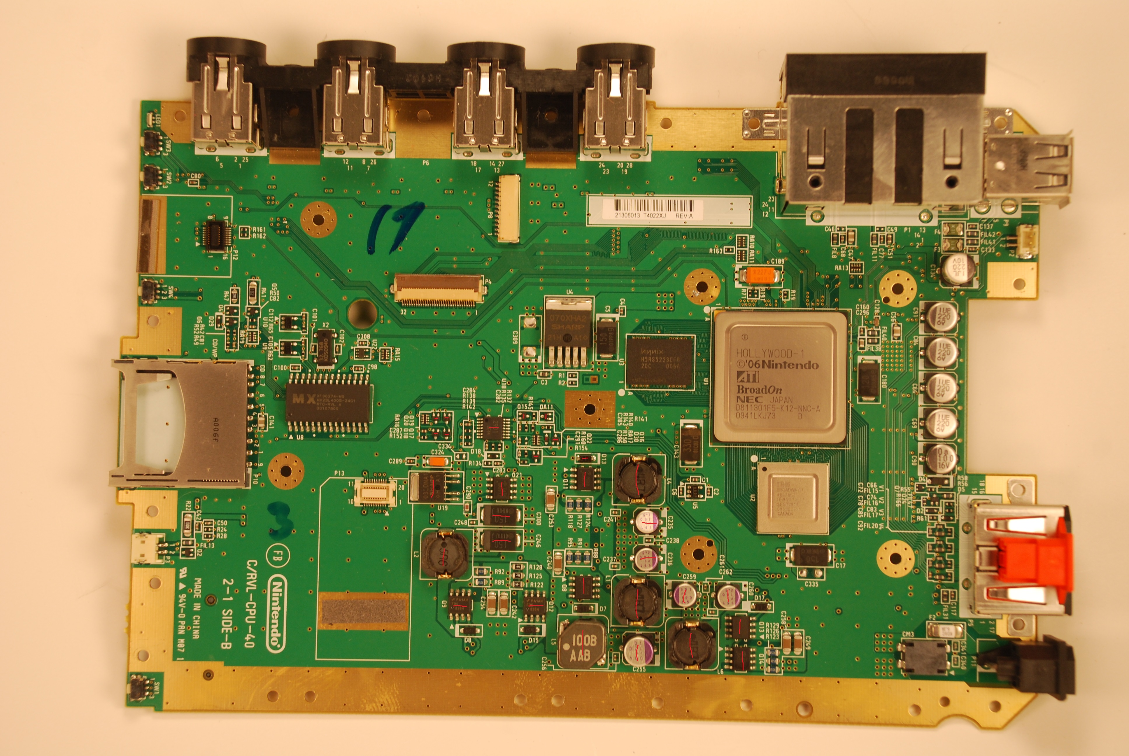
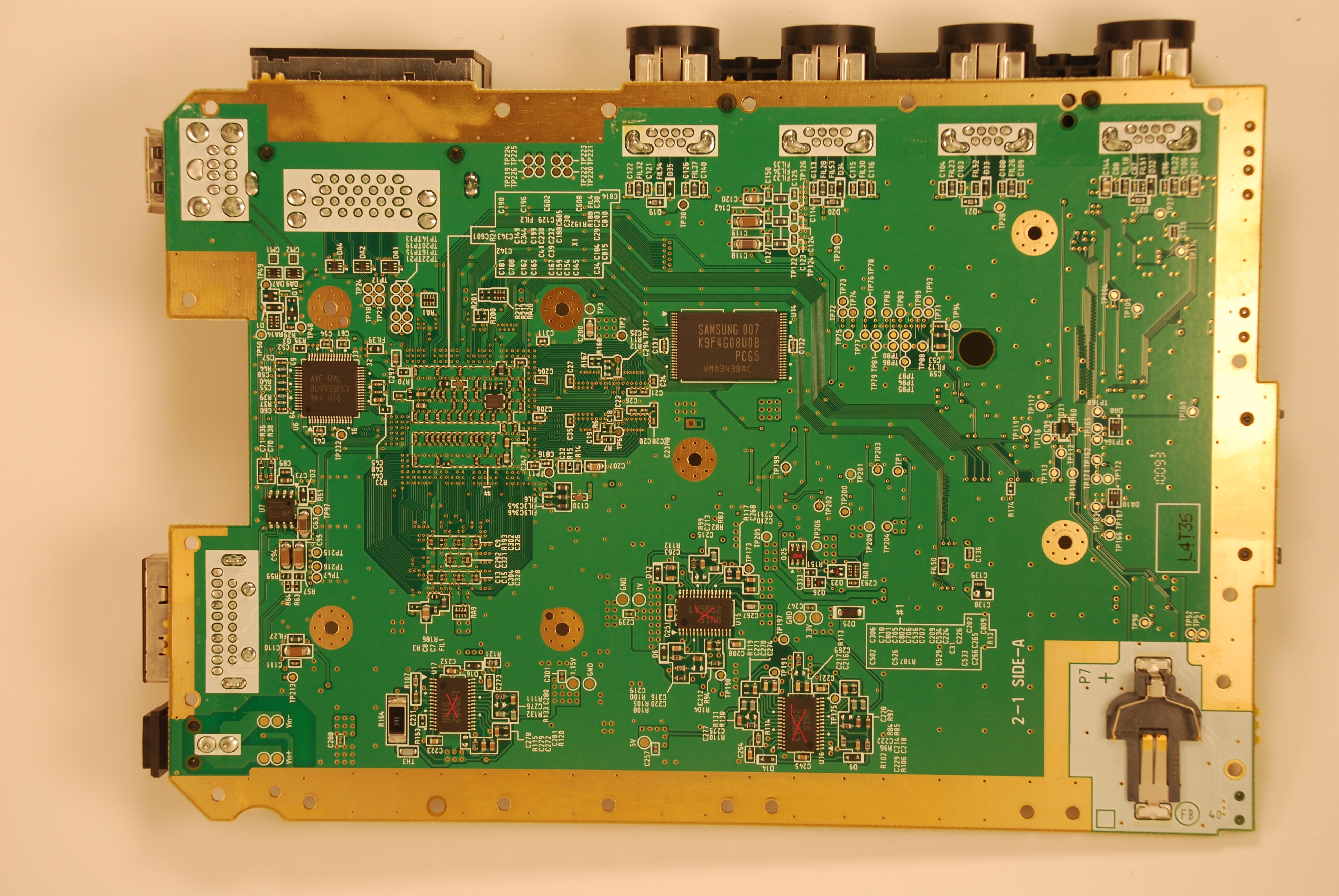
So I got to work on the motherboard! I removed U15, U16, U17, U18, the 3.3v standby regulator, the 5 large electrolytic capacitors on the top in the regulation area, the 5 inductors on top, the 8 8-pinned ics on the top, all of the little transistors near U18 and a few more on the bottom side. Pretty much everything except for the passive components. I have marked on the below pictures in red all of the components I just talked about.
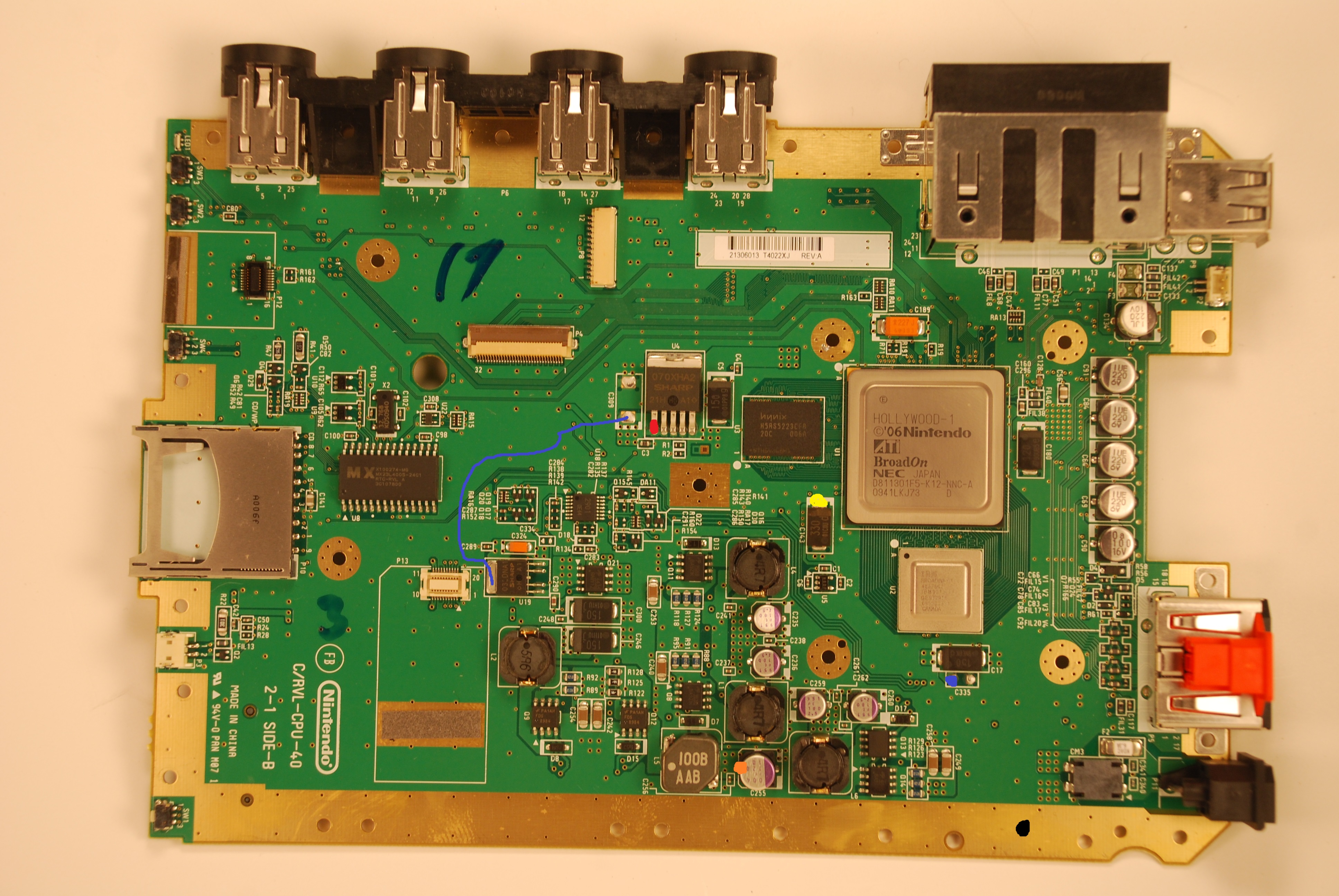
After that I made the below connections on the board to my regulators:
Blue Line: connecting 3.3v Standby line and regular 3.3v line
Orange circle: 5v (When I looked at the Wii compendium this spot on the electrolytic connected with 5v everywhere else I think)
Red Circle: 3.3v
Blue Circle: 1.15v
Yellow Circle: 1v
Black Circle: Ground
When measuring with my multimeter, My 3.3v volt line drops a lot, to under 1 volt. I am not sure what can be causing it as I did no trimming to the board.
Also, I wanted to point out that to test it I was using the regular AV cable and plugging it into my television, and connected the usb drive to the port that was closest to the motherboard. Is there anything that I am missing that would cause the wii not to boot?
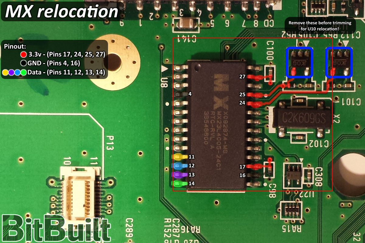
I know that with the OMGWTF trim that you also need to do the U10 relocation, is that necessary when not trimming the board? I suppose my next step will be removing every single little passive component.
I also know that I will not be getting any audio at the moment since the audio preamp is not getting it's 12v. I figured that I wanted to try and get the video and the console working before I messed with the audio. Should I go ahead and attach the battery pack voltage (7.4ish volts I think) to the audio preamp?
I appreciate everyone's help and hope I can solve this soon!
So far I already have my portablizemii installed on the wii and my custom regulators wired up and putting out the proper voltages (I will add those pictures soon)
As of right now I am stuck a little. Since I will not be trimming my wii motherboard, I was looking around the forum to see how I could go about connecting the custom regulators with an untrimmed board. I stumbled on the below thread and found some helpful comments
https://bitbuilt.net/forums/index.p...e-main-regulators-on-the-board.700/#post-7118
In the thread above, Gman said this:
"Remove the large inductors and capacitors that are located outside of the OMGWTF trim. Also most importantly remove U18 and the 3.3v standby regulator. On the back, remove U15, U16, and U17. I usually just pull everything off with pliers and then use a soldering iron to clean up the connections so nothing has shorted. Some boards you can get away with just removing U18, but others I have found it won't work so to be sure, you could just remove everything."
and then Shank said:
"You will also need to connect both the 3.3v and 3.3v standby lines together and power them off of the 3.3v line.
So I got to work on the motherboard! I removed U15, U16, U17, U18, the 3.3v standby regulator, the 5 large electrolytic capacitors on the top in the regulation area, the 5 inductors on top, the 8 8-pinned ics on the top, all of the little transistors near U18 and a few more on the bottom side. Pretty much everything except for the passive components. I have marked on the below pictures in red all of the components I just talked about.
After that I made the below connections on the board to my regulators:
Blue Line: connecting 3.3v Standby line and regular 3.3v line
Orange circle: 5v (When I looked at the Wii compendium this spot on the electrolytic connected with 5v everywhere else I think)
Red Circle: 3.3v
Blue Circle: 1.15v
Yellow Circle: 1v
Black Circle: Ground
When measuring with my multimeter, My 3.3v volt line drops a lot, to under 1 volt. I am not sure what can be causing it as I did no trimming to the board.
Also, I wanted to point out that to test it I was using the regular AV cable and plugging it into my television, and connected the usb drive to the port that was closest to the motherboard. Is there anything that I am missing that would cause the wii not to boot?
I know that with the OMGWTF trim that you also need to do the U10 relocation, is that necessary when not trimming the board? I suppose my next step will be removing every single little passive component.
I also know that I will not be getting any audio at the moment since the audio preamp is not getting it's 12v. I figured that I wanted to try and get the video and the console working before I messed with the audio. Should I go ahead and attach the battery pack voltage (7.4ish volts I think) to the audio preamp?
I appreciate everyone's help and hope I can solve this soon!
Last edited: