Guide Wii Trim Resistances

Nold

real emulation, no hardware
.
.
2021 1st Place Winner
Joined
Jul 16, 2017
Messages
453
Likes
1,644
Location
EU
Portables
5 + 1*π
Hi guys,

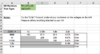
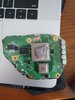
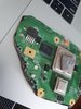
since a lot of new ppl try trimming wiis, i was thinking about collection some common questions & data. So i've started writing down my latest voltage resistances.

I hope some of you could add some more with different trims & revisions!
trim_sheet_preview.JPG


It's an OpenDocument Sheet, but Excel can just open it fine. The archive also includes my first two measurements.

Also: Please only send me values of working trims or otherwise mark the non-working ones & read the notes before measuring!


//Edit 1: Wii-Mini trims would also be very interresting. So simple select trim-type "Custom" and write a note next to it.

Thanks a lot!
 

Attachments

Last edited:
Last I checked, this was a working trim! Can any of you confirm that these values are okay? Thanks in advance!
 

Attachments

  • Screen Shot 2020-10-25 at 9.36.00 PM.png
    Screen Shot 2020-10-25 at 9.36.00 PM.png
    60.6 KB · Views: 1,025
Someone asked me to do my 6 layer wii, here is my values. the 3.3v line is all over the place so I did my best.

edit: forgot to put revision and trim
 

Attachments

Last edited:
working trim RVL-CPU-40
 

Attachments

  • wii resistance.png
    wii resistance.png
    30.6 KB · Views: 866
Completed another trim.

Wanted to post in here to reference. I had some low readings at first on the 3.3v but after sanding and removing the components on the edge as Wesk suggested, I was able to get them to match the higher k range. It is interesting that they have almost double what I typically see on this thread... But was told that it shouldn't be an issue. If anyone has any suggestions on this, let me know!

Before:
1632752005413.png

After removing half cut components on edge of mobo and re-sanding to 1000 grit sand paper:
1632751894173.png
 
1641787570285.png


Hello, I have these values of resistance between points, my trimm type is the one of the basic guide of 6 layers, and my board is rlv-cpu-01, these values are correct?
 
Hello all, I have a quick question regarding resistance values on a trimmed motherboard. It appears I have a short between my 3.3v and 1.8v. Would this be caused by having the LDO removed, because I did that previously. I had not taken the resistance measurement before removing. If not what is the best way to start troubleshooting this? Sand the edges better? Any help is appreciated. Thanks!
 
I wanna share my measurements for my working trim.

RVK-CPU-01.jpg
 
Hi all, I am total noob in the whole trimming art. I did the initial cut of the board and of course it might have gone wrong - tried to follow of course the guide.

Can you post some pics on how you measure and produce the results above? I know it's super basic but i basically use multimeter first time ever so still finding my way around it and how to use in real boards.
(so far trying to place the red/black in what I think were the proper spots gave basically nothing so either I do it wrongly or I bombed the trimming...)
This is a half decent guide to operating a multimeter, particularly the "Measuring Resistance" section. The 20k setting is what we normally use.

Combine with the voltage and ground locations shown in The Definitive Wii Trimming Guide, and you'll be able to populate the table.
 
This is a half decent guide to operating a multimeter, particularly the "Measuring Resistance" section. The 20k setting is what we normally use.

Combine with the voltage and ground locations shown in The Definitive Wii Trimming Guide, and you'll be able to populate the table.

Thank you. I am experimenting with some resistances I have from a raspberry pi kit and works fine. Now I try a bit on the board and if I am doing this correctly I get 0 always.

just in case there is some advice available, I attach my trim, which is terrible compared to the ones I have seen online, so chances are I have messed up things.

Also - I am thinking this might not be the right thread to troubleshoot, as it's more for measurements, so probably will not post here this type of issues, let me know if you agree
 

Attachments

  • 20230101_131819.jpg
    20230101_131819.jpg
    1.6 MB · Views: 409
  • 20230101_131825.jpg
    20230101_131825.jpg
    1.5 MB · Views: 386
Did you sand that trim at all yet? The edges look really rough, and some of those gouges are deep enough to cause concern for the possibility of shorting between layers.
Here's a good plan of action:
  1. Desolder all components on the edges of the board that were cut through
  2. Sand the edges of the board with 120, 220, 320, 400, 600, 800 and 1000 grit sandpaper (numbers don't need to be exact, but it's best to start low and slowly move up the grits until you hit 1000)
  3. Pull off those thermal pads
  4. Clean the entire board with some 91% (or greater) IPA
It also looks like you might have sliced through some NAND traces, but I can't tell without seeing the back.

I do agree that this probably isn't the best place to diagnose this; feel free to message in the Discord or make a new thread here on the forums.
Thank you very much! I will try some of these steps. Meantime I have another Wii board so I can compare - I assume the measurements would work there !! :D
And for anything else I will follow up on Discord. Happy new year!
 
Hi all, I am total noob in the whole trimming art. I did the initial cut of the board and of course it might have gone wrong - tried to follow of course the guide.

Can you post some pics on how you measure and produce the results above? I know it's super basic but i basically use multimeter first time ever so still finding my way around it and how to use in real boards.
(so far trying to place the red/black in what I think were the proper spots gave basically nothing so either I do it wrongly or I bombed the trimming...)
i am also new to measuring resistances, at the 20k ohm setting i am getting very low readings on most of the points, the only ones i can seem to match are the 8-9k resistances of the 3.3v row. i also don’t know where to measure 1.8v i checked the wii training guide and it shows spots for 1v 1.15v 3.3v and 5v but no 1.8v unless i totally misread it.
 
Back
Top