Preface
The Definitive Wii U Trimming Guide only supports WUP-50 Wii U motherboards. WUP-50 motherboards consume much less power than earlier revisions, making them usable for portables. An addendum for earlier motherboard revisions may be released in the future.
Thanks to recent discoveries, the Wii U homebrew scene is rapidly evolving. Various bleeding-edge softmods are under development and the guide will undergo major edits as these softmods become available to the public. For portablizers, this means that some relocations may no longer be necessary! Check the Wii U R&D thread and this guide's changelog for the latest updates.
This guide was developed for the BitBuilt community, but BitBuilt was not involved in the writing of the guide, and is not responsible for its content.
Please note that Wii U portablizing is much more challenging than Wii portablizing! Fine-pitch via soldering (like the Wii AVE relocation) and trace-scratching (like Wii Bluetooth) are mandatory to produce a functional LOLWUT trim. This guide and the information contained within are provided “as-is”, and the trim should only be attempted by experienced modders. Have fun!
Identifying your Wii U’s Motherboard Revision
This trimming guide is intended for WUP-50 Wii U motherboards only. All Wii U consoles have a white sticker on the bottom that indicates motherboard revision. The sticker is located below the larger sticker indicating storage capacity, and has a 2D barcode and a lot code. The last two digits of the lot code indicate motherboard revision.
01 = WUP-01 ✗
20 = WUP-20 ✗
30 = WUP-30 ✗
40 = WUP-40 ✗
50 = WUP-50 ✓
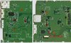
8GB WUP-001 consoles never contain WUP-50 motherboards. WUP-50 motherboards are only found in 32GB “Deluxe” WUP-101 consoles. However, as shown in the photos, not all WUP-101 consoles contain WUP-50 motherboards. Additionally, WUP-101 consoles can be black or white. Therefore, unlike the Wii, shell color is not an accurate way to determine board rev.
Always refer to the sticker on the underside of the console to determine motherboard revision! You can also look inside the Wii U's SD card slot to see the motherboard revision code.
Prerequisites
Before trimming, you must obtain the following:
- Wii U with a WUP-50 motherboard, softmodded with Tiramisu and Aroma.
- Follow the Wii U Hacks Guide to softmod your Wii U with autoboot Tiramisu
- Don’t forget to make a full NAND backup! The Wii U is prone to filesystem corruption and having a backup is essential.
- Then follow the Aroma guide to install autoboot Aroma
- A Wii U GamePad that is the same region as your console (mandatory to softmod and play games)
- Write down your Wii U console's pair code (4 suit symbols) so you can re-pair a GamePad, if needed!
- Note: out-of-region GamePads may pair using udpih or certain Aroma plugins, but if their firmware is not up-to-date, they will cause your console to bootloop!
- Put Wii U console into GamePad sync mode. Its 5GHz SSID will show up on nearby PCs or phones. The last byte is the pair code, but you need to convert it to binary. (89 -> 10001001)
- Once in binary, split it into 4 bytes (10 00 10 01), which equates to 2 0 2 1
- 2 0 2 1 pair code = diamond spade diamond heart
- Non-SDHC SD card that is <2GB in size. 1GB or smaller is preferable
- Raspberry Pi Pico or another RP2040 board (RP2040 Zero is preferred due to its compact footprint)
Pico de_Fuse Setup
de_Fuse is a Wii U hardware exploit discovered by ShinyQuagsire23. His Pico de_Fuse modchip runs stroopwafel, a softmod that patches out the disc drive. Pico de_Fuse requires some softmodding/dumping to be performed before trimming.
If you did not dump otp.bin while softmodding your Wii U, follow the instructions below to dump it with udpih. If you already dumped otp.bin, copy it to your PC and skip to downloading de_Fuse.zip.
- Flash udpih to your Raspberry Pi Pico or RP2040 Zero by following the instructions on the GitHub page.
- Copy recovery_menu onto your SD card and boot it by following the linked instructions.
- Select the third option to dump your Wii U’s OTP and SEEPROM.
- If you want, you can select Submit System Data to contribute your Wii U’s info to wiiu.gerbilsoft.com. Shutdown afterwards.
- Copy otp.bin and seeprom.bin from the SD card to your computer.

- Download the latest release of ShinyQuagsire23’s de_Fuse.zip
- Format your non-SDHC SD card (<2GB) and flash boot1.img to it using Win32DiskImager.
- Copy fw.img and the wiiu folder from de_Fuse.zip and the otp.bin you dumped earlier to your SD card.
- Create a file on the SD card named minute.ini and copy the following text into it:
[boot]
autoboot = 1 - Finally, flash pico_defuse.uf2 to your Pico or RP2040 Zero. Once you wire it up after trimming, Pico de_Fuse will automatically patch out the disc drive.
About vWii
The vWii is the Wii U's built-in Wii environment. It has a couple major caveats that make it unsuitable for Wii U portables at this time.
- vWii cannot start without the disc drive.
- Even with Priiloader installed and homebrew like USBLoaderGX set to autoboot, the vWii crashes when booting if the disc drive is absent, or SATA devices are disabled via either SEEPROM or Stroopwafel.
- It's likely this will be fixed via softmodding in the future. However, for the time being, the vWii is unusable for portables.
- Furthermore, games loaded from within vWii cannot be controlled with the Wii U GamePad.
- GC/Wii VC injects installed to the Wii U Menu, on the other hand, can be controlled with the GamePad, if you enable that option during injection.
- A Wii U Nintendont forwarder like CrisMMMod.ver.7.30 also allows Gamecube games to be played with the Wii U GamePad.
- The vWii cannot load Wii or Gamecube games from the same USB drive you install Wii U games to. You must load Wii games from a second USB drive or the SD card(or use experimental partitioning hacks like Stroopwafel's USB Shrinkshift)
- Pico de_Fuse normally requires a non-SDHC SD card (<2GB), which obviously precludes the storage of GC/Wii backups on the SD card.
- However, Pico de_Fuse v0.8 and higher support flashing boot1_slccmpt.img to NAND, allowing the use of larger SD cards. See the release notes on GitHub for details about how to flash boot1_slccmpt.img. Note that the Wii U will not boot without an SD card if you choose this route.
Additional Softmodding Setup (optional, vWii only)
vWii is currently unusable without a disc drive connected. This section of the guide will only become relevant once the disc drive dependency is patched out. Until then, it can be ignored; use VC injects to play Wii and GC games.
- Download the latest vwii-compat-installer release from GitHub and place it in /wiiu/apps/compat-installer on your SD card.
- Download the latest Priiloader_vX.zip and PriiloaderWiiUForwarder.zip from GitHub and extract them both to the root of your SD card.
- Insert the SD card into your console and hold X on power-up to start the EnvironmentLoader.
- Select Tiramisu, then in the Boot Selector select the Homebrew Launcher.
- Select compat-installer from the Homebrew Launcher and follow the instructions to install the vWii Homebrew Channel.
- Power off your Wii U. Power it on again while holding Start to enter the Boot Selector.
- Select the vWii System Menu. If you have not already paired a Wii remote with your Wii U, do so once the vWii System Menu loads.
- Point the Wii remote at the GamePad and select The Homebrew Channel.
- Select Priiloader Installer and follow the instructions. Power off the Wii U once complete.
Please note that RVLoader 1.6 / Hiidra do not work properly on vWii. Instead, it is recommended to install cIOSes and patch IOS 80 to facilitate loading backups.
- Download d2x_cIOS_Installer and place the d2x-cios-installer folder into the apps folder of your SD card.
- Download Patched IOS 80 Installer for vWii and extract it to the root of your SD card. Put the SD card back into your Wii U.
- Follow the instructions listed under Installing cIOSes on wiiu.hacks.guide.
- Follow the instructions listed under Patching IOS 80 on wiiu.hacks.guide.
Once again, please read through the About vWii section above to understand the vWii’s rather severe limitations!
Trimming
Important pre-trim preparation!
- Before disassembly/trimming, configure the Wii U’s TV settings to 480i non-HDMI output (Wii AV cables). This will make testing the trim with composite video possible. If you do not do this, and anything goes wrong with the GamePad (it desyncs or there is 1.1V or 1.25V instability), you will be forced to rewire HDMI.
- Before disassembly/trimming, disable Auto Power-Down and Standby Functions in the Wii U's Power Settings. Make sure the Quick Start Menu is also disabled. This will make testing with the GamePad easier.
- Remove R116, located near the HDMI port and U14, and save it for later. It will be reattached during the video relocation. If you lose R116, it can be replaced with any 0402 or 0603 size 510Ω resistor.
Only one trim is supported: the LOLWUT trim. Its dimensions are approximately 110mm x 80mm.
Remove any components the trim line intersects before trimming! Trim outside the lines, and sand toward the lines with increasingly fine grits of sandpaper (finish with at least 600 grit). The Wii U motherboard is 6 layers with very tight layer spacing, so careful sanding is imperative to avoid shorts.
Once sanded, visually inspect the edges of the mobo to ensure there are no shorts. Here are some ballpark resistance values for the voltage rails (see the Relocations section for voltage rail locations.) As long as the resistances are the same order of magnitude as the listed values, and there are no dead shorts (0Ω), you’re good.
- 1V to GND: ~10Ω
- 1.1V to GND: ~1.7kΩ
- 1.15V to GND: ~20Ω
- 1.25V to GND: ~700Ω
- 1.5V to GND: ~170Ω
- 3.3V to GND: ~25kΩ
Relocations
The Wii U requires the following relocations in order to boot and play games. As of Jan. 2024, all relocations are mandatory. (2/1/24: Pico de_Fuse is not mandatory when using ISFSHax. The trim guide will be updated soon to cover ISFSHax as well as other recent softmodding developments.)
Please follow the checklists in each section to ensure you’ve made all the necessary connections. You can also find photos of most of the relocations in the Wii U R&D Thread, where LOLWUT trim development was documented.
☐ SMC and RTC
☐ NAND and eMMC
☐ Pico de_Fuse modchip
☐ 2.4GHz Wi-Fi module
☐ 5GHz GamePad module
☐ Bluetooth module
☐ SD card (for homebrew)
☐ USB (for games)
☐ Power / custom regulators
☐ Video and Audio
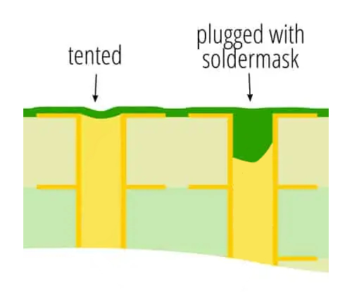
Be advised that the WUP-50 motherboard has plugged vias. Unlike tented vias, the soldermask actually penetrates into the via barrel, blocking it and preventing the insertion of magnet wire. When soldering magnet wire to vias on the Wii U, scratch the soldermask off the via and tin it liberally. Then solder the magnet wire to the “solder bubble” created on top of the via.
SMC and RTC
The SMC (system management controller) handles the Wii U’s power button and power/status LEDs. The RTC (real-time clock) performs boot, power-up/power-down, and clock functions. Both are required for the Wii U to function. You must trim an SMC/RTC daughterboard from the motherboard to relocate these two ICs. In the future, a custom PCB to relocate the SMC/RTC may be released.
Wii U motherboards have two separate RTC footprints, one on the top layer and one on the bottom layer. Only one of the RTCs is ever populated, and which one is populated is seemingly random. A top-side RTC is preferable as this allows the SMC/RTC daughterboard to be trimmed smaller, but both variants are usable.
Top-side SMC/RTC Daughterboard Trim
Bottom-side SMC/RTC Daughterboard Trim
Remove any components the trim line intersects before trimming! Treat this daughterboard as you would the main motherboard trim. Trim outside the lines, and sand toward the lines with increasingly fine grits of sandpaper (finish with at least 600 grit). Check for dead shorts (0Ω) between 3.3V and GND after sanding.
SMC and RTC Connections
- The solder points in the diagram are universal to both top and bottom RTC variants.
- There are seven 3.3V points on the SMC/RTC daughterboard that need to be reconnected. Wire them together with magnet wire as shown, and supply 3.3V to any one of the points. Supply GND to the marked via, the screwhole, or any other portion of GND plane.
- The power button and eject button lines are active-low. Connect these lines to momentary, normally-open switches to GND. The eject button is used to navigate the de_Fuse serial console menu, so relocating it is recommended.
- The Red, Blue, and Yellow LEDs indicate de_Fuse and console power status. The LED pins supply current, so make sure the other side of the LEDs are connected to GND. Connect the LED pins to the LEDs via series ~1kΩ resistors. You can deadbug the resistors onto the Wii U’s front IO board LEDs as shown below, or wire up your own LEDs.
- If you wish to preserve real-time clock functionality, connect a coin cell to the RTC B+ trace and GND.
TP148 Connection
You must connect a ~10kΩ resistor between TP148 and 3.3V.
SMC and RTC Relocation Checklist
☐ All SMC/RTC 3.3V points soldered together with magnet wire
☐ 3.3V and GND reconnected to SMC/RTC daughterboard
☐ 10kΩ resistor soldered between TP148 and 3.3V
☐ SMC SDA, SCL, and RESET reconnected to SoC (3 wires)
☐ Power/eject button and LEDs reconnected to SMC (5 wires + GND)
☐ RTC reconnected to SoC (6 wires)
☐ SMC and RTC reconnected to BT, 2.4GHz and 5GHz modules (see individual module relocation sections)
☐ Coin cell reconnected to RTC (optional)
NAND and eMMC
The TSOP NAND and eMMC store vital system files and are required for the Wii U to function. Like the SMC and RTC, you must trim a NAND+eMMC daughterboard from the motherboard to relocate these two ICs. In the future, a custom PCB to relocate the NAND and eMMC may be released.
Remove any components the trim line intersects before trimming! Treat this daughterboard as you would the main motherboard trim. Trim outside the lines, and sand toward the lines with increasingly fine grits of sandpaper (finish with at least 600 grit). Check for dead shorts (0Ω) between 3.3V and GND after sanding.
34AWG or thinner magnet wire is highly recommended for this relocation.
NAND and eMMC Relocation Checklist
☐ NAND rewired to SoC (17 wires)
☐ eMMC rewired to SoC (6 wires)
☐ 3.3V and GND reconnected to NAND+eMMC daughterboard
Pico de_Fuse
If using an RP2040 Zero, you can desolder its 3.3V LDO and USB-C port after programming to slim down the board.
When powering up the motherboard, you should see flashing blue and red LEDs as the modchip de_Fuses the console, and a static purple (blue+red) LED once de_Fusing is complete and the system is booting.
Connection list:
- GPIO2 to D0 on motherboard
- GPIO3 to D1 on motherboard
- GPIO4 to D2 on motherboard
- GPIO5 to D3 on motherboard
- GPIO6 to D4 on motherboard
- GPIO7 to D5 on motherboard
- GPIO8 to D6 on motherboard
- GPIO9 to D7 on motherboard
- GPIO10, GPIO11, GPIO12, GPIO13 to TP176 (EXI0 MISO) on motherboard
- GPIO14 to TP101 (EXI0 CLK) on motherboard
- GPIO15 to TP144 (NRST) on SMC/RTC daughterboard
- GPIO18, GPIO19, GPIO20, GPIO21 to D6 on motherboard
Debug Connections
34AWG or thinner magnet wire is highly recommended for this relocation.
EXI Connections
SMC/RTC Connection
Pico de_Fuse Relocation Checklist
☐ 3.3V LDO removed from Pico
☐ 3.3V and GND wired to Pico
☐ Debug connections wired from Pico to motherboard (8 wires)
☐ EXI connections wired from Pico to motherboard (2 wires)
☐ NRST wired from Pico to SMC/RTC daughterboard (1 wire)
2.4GHz Wi-Fi Module
The Wii U’s 2.4GHz Wi-Fi module is required for the system to boot, and is used to connect to the internet and transfer games and homebrew.
The Wii U Wi-Fi module does not have testpoints, so you must solder directly to the original connector footprint. Magnification and 34AWG or thinner magnet wire is highly recommended for this relocation.
Data Lines
SMC/RTC Connections
SoC Connection
2.4GHz Wi-Fi Module Relocation Checklist
☐ Wi-Fi module data lines wired to motherboard (6 wires)
☐ Wi-Fi module rewired to SMC/RTC daughterboard (2 wires)
☐ Wi-Fi module rewired to SoC (1 wire)
☐ 3.3V and GND wired to Wi-Fi module
☐ One or more antennae reconnected (optional)
5Ghz GamePad Module
The Wii U’s 5GHz GamePad wireless module sends and receives data to/from the Wii U GamePad. Since many Wii U games require a GamePad to be connected before the game will even load, relocating the 5GHz module is required.
The Wii U 5GHz module does not have testpoints, so you must solder directly to the original connector footprint. Magnification and 34AWG or thinner magnet wire is highly recommended.
Pins 18 and 19 need pulldown resistors connected between the module pin and GND. Pin 18 needs a 10kΩ resistor (R266) and pin 19 needs a 47kΩ resistor (R689). R266 and R689 are located opposite the 5GHz module connector on the Wii U motherboard, and can be harvested before or after trimming.
Data Lines and TP99
SMC/RTC Connections
5GHz GamePad Module Relocation Checklist
☐ 10kΩ resistor wired between module pin 18 and GND
☐ 47kΩ resistor wired between module pin 19 (or TP99) and GND
☐ 5GHz module rewired to TP99 (1 wire)
☐ 5GHz module rewired to SMC/RTC daughterboard (2 wires)
☐ 3.3V and GND wired to 5GHz module
☐ At least one antenna reconnected, or wired directly to GamePad
Bluetooth Module
The Wii U’s Bluetooth (BT) module is required for the Wii U to boot. It also handles syncing controllers. Only non-GamePad controllers (Wiimotes, Pro Controller, Bloopair) connect to the console via the BT module. While initial GamePad syncing is triggered by the Sync button, the GamePad only communicates via the 5GHz module once connected.
Some Wii U BT modules have testpoints on the back, but most do not. If your BT module lacks testpoints, you must solder directly to the original connector footprint.
Magnification and 34AWG or thinner magnet wire are highly recommended for this relocation.
Sync is active high. Temporarily connect sync to 3.3V to trigger controller syncing.
Data Lines
SMC/RTC Connections
SoC Connection
Bluetooth Relocation Checklist
☐ BT data lines wired to motherboard (2 wires)
☐ BT module rewired to SMC/RTC daughterboard (3 wires)
☐ BT module rewired to SoC (1 wire)
☐ 3.3V and GND wired to BT module
☐ Sync button relocated (optional)
SD Card
An SD card is mandatory for Pico de_Fuse and Aroma (homebrew). Relocating it requires scratching and soldering directly to traces next to the Wii U SoC. Magnification and 34AWG or thinner magnet wire are highly recommended.
Short the CD (card detect) and WP (write protect) traces on the motherboard to GND. If this is not done, the Wii U will not mount or read the SD card. Since SD card slot pinouts vary, refer to the pinout of your particular SD card slot when connecting it to the motherboard.
SD Relocation Checklist
☐ 3.3V and GND connected to SD card
☐ SDIO wired from SD card to motherboard (6 wires)
☐ CD and WP on motherboard shorted to GND
USB
A USB drive is recommended to install and run games. (While you can install games to the Wii U’s eMMC, the 32GB space runs out quickly.)
The rear USB port buses (USB0 and USB1) are recommended, since they have vias you can solder to. Use tightly twisted magnet wire for D+ and D-. Wire 5V and GND directly to the USB port/drive.
USB Relocation Checklist
☐ 5V and GND connected to SD card
☐ USB data lines wired to motherboard (2 wires)
Power / Custom Regulators
The Wii U requires 7 voltage rails:
- 1V @ 9A (Latte)
- 1.15V @ 5.5A (Espresso)
- 1.1V @ ~100mA (DRH-WUP-1)
- 1.25V @ ~150mA (DRH-WUP-1)
- 1.5V @ ~1A (RAM)
- 3.3V @ ~400mA (video, SD, de_Fuse)
- 5V (for USB and accessories only)
There are a couple options for custom regulators:
- YveltalGriffin’s Bistro Wii U regulator board is open source on GitHub and generates all 7 voltage rails from 1S lithium-ion batteries.
- Off-the-shelf TI regulator modules
- PTH08T210WAH for 1V
- PTH08T240WAH for 1.15V
- PTH08080 for 1.5V, 3.3V, 5V
- PTH08080 or smaller linear regulators for 1.1V, 1.25V
Regardless of the custom regs you use, your battery pack should be able to deliver at least 7A continuously for safe operation. 1S4P Samsung 50E, 1S2P/1S4P Samsung 50S, and 1S4P Samsung 35E cells are good configurations.
Voltage Relocations
- Supply 1V and 1.15V to the bottom side of the motherboard with short, 18AWG or thicker wire.
- You must connect two dedicated 18AWG or thicker GND wires for 1V and 1.15V.
- 1.5V can be wired with 24AWG. Connect an additional GND wire to the underside of the motherboard, near the 1.5V plane.
- The other rails are low current and only require 28AWG minimum.
- You only need to supply 1.1V, 1.25V, and 3.3V at one of their marked locations.
Q1077/Q1078 Removal and Bypass
Locate Q1077 and Q1078 on the underside of the motherboard. Desolder both Q1077 and Q1078 and bypass them with wire as shown.
Q1077 Bypass
Q1078 Bypass
Power Relocation Checklist
☐ Q1077 removed and bypassed
☐ Q1078 removed and bypassed
☐ 1V, 1.15V and two GND wires (18AWG+) reconnected to motherboard for SoC
☐ 1.5V and one GND wire (24AWG+) reconnected to motherboard for RAM
☐ 1.1V, 1.25V reconnected to motherboard for DRH
☐ 3.3V connected to motherboard, Pico de_Fuse, and SD card
☐ 5V connected to fan and USB (optional)
☐ GND connected to all peripherals and daughterboards (SMC/RTC/NAND/eMMC/SD/Pico de_Fuse/fan/USB/etc.)
Video and Audio
The Wii U can output composite video, component video (YPbPr), and HDMI. Composite video is limited to 480i; component can output 480i, 480p, 720p, 1080i, and 1080p; HDMI can output 480p, 720p, 1080i, and 1080p. 480i and 480p output anamorphic widescreen; higher resolutions are true 16:9 widescreen. The Wii U can only output either analog video or HDMI video at once; it cannot output both simultaneously. The system settings menu controls resolution and which outputs are active.
There are three options for console audio: analog audio, digital audio (I2S), and audio over HDMI. You can also rely solely on the GamePad’s audio, if you wish. The Wii U does not have an I2S MCLK signal, so its digital audio is incompatible with the U-AMP; however, it may work with other I2S amplifiers that don’t require MCLK.
Mode must be connected to 1.25V if you are using component video with a resolution of 480p or higher. If you do not connect mode to 1.25V, the Wii U will only output 480i over component. Mode is unused when outputting HDMI.
R116 relocation
Solder R116 between pin 3 and pin 8 of U14. If you didn’t keep the original R116, you can use any 0402 or 0603 sized 510Ω resistor. A convenient location for reattaching R116 is shown below.
Video and Audio Relocation Checklist
☐ R116 relocated
☐ Analog, digital, or HDMI audio rewired (optional if using GamePad audio)
If using composite/component:
☐ Non-HDMI output selected in system settings
☐ Composite or component wired to screen
☐ If using component @ 480p or higher, mode wired to 1.25V
If using HDMI:
☐ HDMI output selected in system settings
☐ HDMI wired to screen (x4 TMDS pairs, DDC I2C, GND)
☐ HPD (TP10) wired to 5V
Cooling
The Wii U consumes much more power than the Wii, PS2, or Dreamcast, and therefore generates much more heat than those consoles. A large heatsink and fan are required to keep the console from overheating and crashing.
One compact setup that’s known to work well is a 45x45x10mm heatsink paired with a 50x40mm 5V blower fan as seen here in the R&D thread.
Troubleshooting
This section briefly covers some common issues and how to address them. Keep in mind the Wii U is a complex, delicate system and not as well-understood as the Wii.
- No display on GamePad: 5GHz module isn’t connected properly, or 1.1V or 1.25V rails are unstable. Ensure at least one 5GHz module antenna is connected, or coax is hardwired to GamePad.
- Console hangs when loading games or entering Settings menu: 2.4GHz Wi-Fi module isn’t connected properly.
- Orange light: SD card isn’t being detected. Did you short CD and WP to GND? Is the SD card properly formatted and wired?
- System is extremely slow/unresponsive: Low 1.15V rail voltage, poor SD card wiring, poor eMMC wiring, or filesystem corruption (see next bullet point)
- Error 160-2215, Error 160-0103: May be filesystem corruption. Try restoring a NAND dump via the Pico de_Fuse serial console.
Changelog
- 02/01/2024: Updated vWii section to reflect results of recent testing and added disclaimers about upcoming guide changes
- 02/01/2024: Added recommendation to disable Auto Power-Down, Standby Functions, and Quick Start Menu
- 02/07/2024: Fixed Eject button pinout in SMC/RTC diagram
- 04/01/2024: Added GamePad PIN brute force procedure thanks to Lazr1026
Credits & Acknowledgments
- Motherboard scans, trim development and testing by @YveltalGriffin
- Guide and diagrams created by @YveltalGriffin
Special Thanks:
- ShinyQuagsire23, for Pico de_Fuse and stroopwafel
- @Crazzyleprechaun, for pioneering the wireless module relocations and trim dev support
- @thedrew, for alerting the BB community at large to the WUP-50
- @Shank and @Nold, for their initial Wii U research and theorycrafting
- @Redherring32, for sending me a Japanese GamePad and proofreading the guide
- @CrashBash, @cheese, and Noah for providing BitBuilt
- @ShockSlayer, for inspiring me to start portablizing in earnest, and BB’s trim naming conventions
Last edited:
")