Worklog Purple G-Wii Rev 2 Build

Joined
Oct 7, 2021
Messages
8
Likes
5
Hi all, so I'm new to the portablising community and decided to build a G-Wii Rev, had my case printed by Gman. I'm gonna try and do a worklog but it'll be awful and missing stuff probable ahah, hope its okay though

DAY 1


1635115792470.png


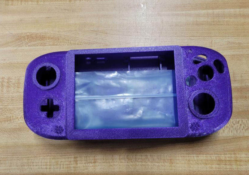
This is my case as it came from Gman, so I decided so start with getting some controls in, I have a PCB set from Ethan (Pickles on Discord). The analogue stick went in real easy, and the buttons weren't too hard to do, I trimmed them with wire cutters, sandpaper and a craft knife. I know that's not the best way but my step dad has my dremel and he's self isolating so I made do.
1635115952626.png


Also got the PD screwed into the bottom part of the case

DAY 2

Today I thought I'd try and get batteries in and wired up to the PMS and wire the PD to it also.

1635116050303.png


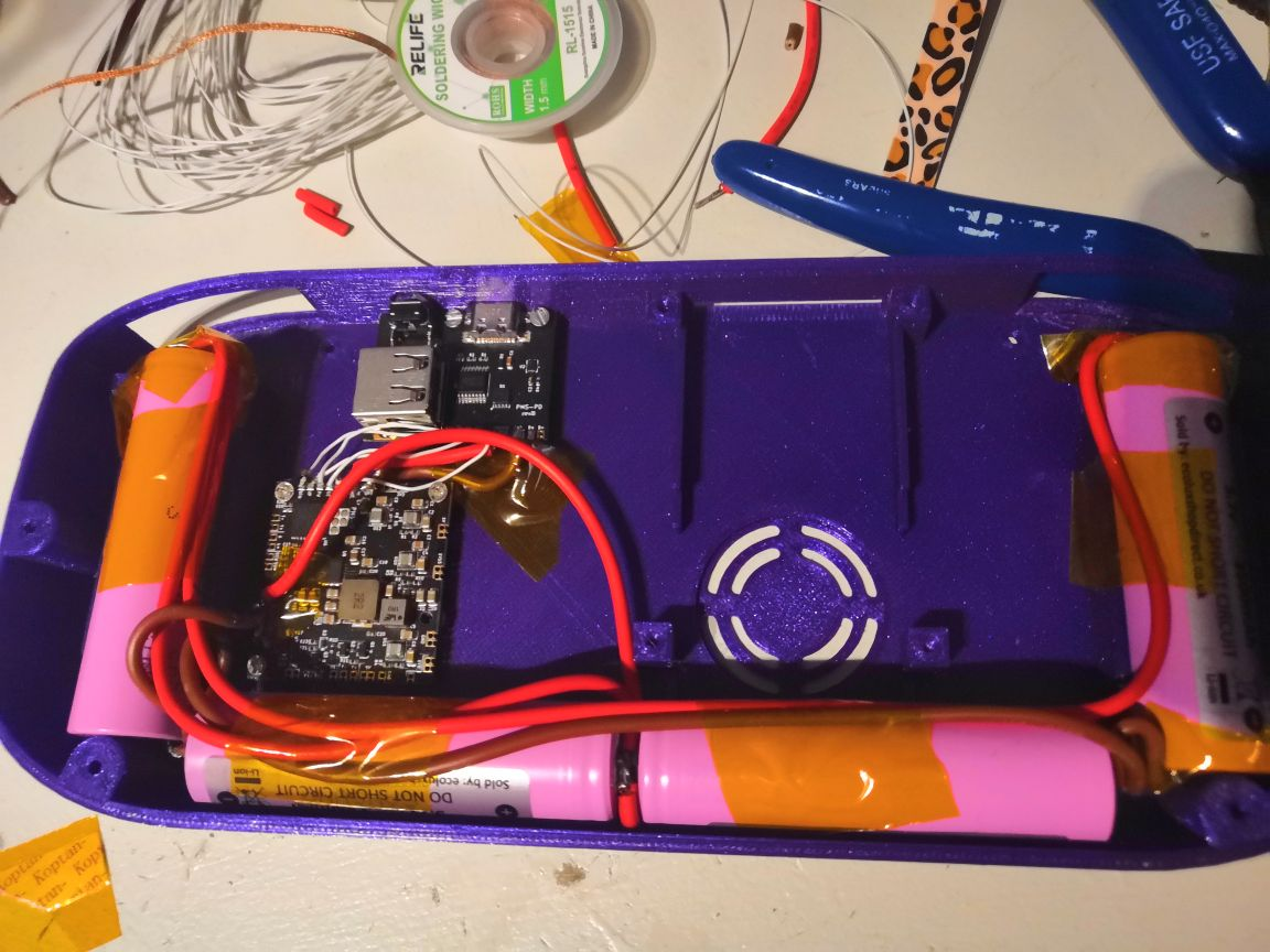
Unfortunately my fan is still not here from china (currently missing Fan, Heatsink, Mushy buttons and Screen :-( ). But I really wanted to test if it worked
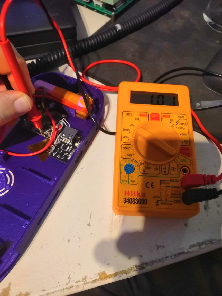
so I read on a post somewhere that if you check the voltages on the PMS you can be reasonably sure it works, so I did just that. Connected my multimeter
and held the power button down and I got the voltages!!!

1635116195424.png


I also decided to try the USB passthrough, and this is where things went a bit awry. I plugged the PD into my PC via USB with my SD reader in the PD and got nothing.
I asked Cyframe for help and we went through a few things, I'd already checked continuity and checked for shorts but I checked them again and found no issue, so I was worried.

However, I messaged GMan, showed him what I did and said I was following the schematic and attached a pic. Gman pointed out I was using the Rev A schematic not the Rev B. Doh!!!

With the wiring changed to match the Rev B, all is well and I have USB passthrough, I also cut the positive wire to my batteries from the PMS so I'm not working on a live circuit after
being warned by Cyframe.

How am I doing?

I was thinking about doing the initial wiring for the GC+ to my control PCBs although I'm wondering, Is this inadvisable since I don't already have my screen or would it be fine?
 
Joined
Jul 9, 2020
Messages
227
Likes
498
Good problem solving dude. Moving forward with what you can and utilizing the community for help. Im not sure about everyone else but I usually get my wii trimmed and booting before doing controls and satellite boards. But I suppose any order could work... Its nice to have controls early on too. :)

I love that you're removing the battery lines so you're not working on a live circuit... ive been feeling like integrating an internal tiny switch on the b- so i can just cut off the circuit whenever i want to work or test without fear of damaging anything too... nice practice. Good to see... you can trim and test your wii without having your screen and driver if you have a TV that has composite input. Just take an old RCA cable and solder the shield to ground and the tip to the composite via coming off of AVE.

1635225306908.png

TP 80 is ground and that yellow dot over the via is the composite line.

Cheers mate. Good job!
 
Joined
Oct 7, 2021
Messages
8
Likes
5
DAY 3

Received a package from China today :-) . It contained some part I've been waiting for to progress, namely the Fan, Heatsink and mushy buttons.

Straight away I broke the soldering iron out and got the fan installed and I can confirm I got fan spin :-)))))))))

Also did a test fit of the copper heatsink.

1635279221570.png


Next I thought I'd get wires attached to the select button and the I could put the left analog stick in place which I did.

1635279323058.png

1635279384676.png


It's nice to see the "face" of the console getting there.

Then decided I'd get the shoulder buttons sorted, did a test fit for the feel and it felt good so I wired up some wires
to the switches and did another test fit. I then glued the two switches in place on each side.

I did need to pull the right trigger out again and do some minor sanding as the button appeared to be getting stuck but as is well now (I think)

1635279566558.png
(plz noone try and steal my fingerprint from the hot glue in that picture please thank you :-p )

I'm still waiting on the screen but that's the last part I need to finish the project. I'm going to attempt the trim tomorrow I think
and then hook a composite cable up to my TV to check I didn't goof it up as SparkleBear suggested

Hope I'm doing okay
 
Joined
Jul 9, 2020
Messages
227
Likes
498
Nice job bud. Did you get a copper plate too? since there is only one heat sink in, you'll need to bond the copper plate to the heat sink and eventually use thermal compound so both chips get adequate cooling.
 
Joined
Oct 7, 2021
Messages
8
Likes
5
Nice job bud. Did you get a copper plate too? since there is only one heat sink in, you'll need to bond the copper plate to the heat sink and eventually use thermal compound so both chips get adequate cooling.
Yes I have a chunk of 1mm copper plate, I've got it marked ready to cut tomorrow.
 
Joined
Oct 7, 2021
Messages
8
Likes
5
DAY 4

So I decided that today would be the big day where I finally did the trim.

I consulted the Wii trimming guide and cross-referenced with other G-Wii builds and marked out the trim (meant to take a pic and forgot).

The trim went okay but very slow, the cutting discs I got were awful and the diamonds kept coming off the edge leaving a blunt disc but I got there. (guess that's what I get for getting cutting discs off Amazon lmao)

1635452839078.png

1635452859979.png


I cleaned the dust off with alcohol and a brush in the sink and then sanded the edges (avoiding the NAND lines). however, I ran into an issue, I was told the trim for the G-Wii was really tight and when I tried to fit the trimmed board it was too big the fit in the G-Wii. I inspected the trimmed board and some pictures and saw I left too much PCB next to the NAND lines, so I got the cutter out again and trimmed along the long edge again, getting really close to the NAND lines. Cleaned the board, Sanded it and Voila, a board that fits in the case.

1635453106058.png


Next I thought I'd test if the board survived my trimming effort, so I wired up the power and a composite cable to my TV (Screen is still not here so @SparkleBear said to hook up a composite cable to test, Thanks for that advice man). I turned the power on and nothing...... So I was pretty worried at this point that i broken something, then I realised that I hadn't hooked up the U10 emulation, got that wired in, turned the power on and nothing......

Also in the photo below I'd cut the copper plate to fit and thermal Adhesived it to my heatsink.

1635453354023.png


So I asked Cyframe for help and he said "send me a picture of your voltage wiring" so I turned the board over and instantly spotted the problem, some of the pads from where I removed the LDO where shorted so I cleaned those up, tried again aaaaaaand IT WORKS.

1635453418480.png


I then wired up the PMS I2C connections, 1 went okay and I made a total hash of solder to the SDW via but Cyframe pointed me to a capacitor that I could solder to for the SDW line which went well. Not sure if it works yet though.

Anyway, next challenge, USB... I broke out the magnet wire and twisted the wires, soldered them in and didn't get anyway, no USB at all. I bashed my head against the wall for like 2 hours. In the end I totally redid the USB twisted pair on the other USB line and after some fiddling, it also works. Now I can boot into RVLoader.

1635453616256.png


All in all a pretty successful day. Big thanks to @Gman , @Cyframe and @SparkleBear for your help yesterday.

DAY 5

So, I still have no fucking screen, So I'm looking for jobs to do in the meantime.

Afaik I have to solder -

- The MX
- Audio
- Video
- Controller

So I decided that I'd do the MX reloc today. Started by wiring the voltage, coin cell line, and data lines to the MX then mounting it on the Wii MOBO.

All went pretty well then, I soldered to the vias for 3.3V and the data lines and the Ground I got off an unused screw post.

Switched it on and well, nothing blew up but also I have no controller to navigate the menus to see if it works or not so I think it's relocated although we'll have to wait till I have a controller to find out. (SparkleBear recommended wiring a GC controller to it but I don't have one so that's off the table haha)

1635453885788.png


Hope I'm doing okay? It's good to finally feel I'm getting somewhere just need that damn screen now
 

Stitches

2 and a Half Dollarydoos
Staff member
.
.
Joined
Feb 5, 2017
Messages
3,847
Likes
3,024
Location
Banana Bender Land, Australia
Portables
6
DAY 4

So I decided that today would be the big day where I finally did the trim.

I consulted the Wii trimming guide and cross-referenced with other G-Wii builds and marked out the trim (meant to take a pic and forgot).

The trim went okay but very slow, the cutting discs I got were awful and the diamonds kept coming off the edge leaving a blunt disc but I got there. (guess that's what I get for getting cutting discs off Amazon lmao)

View attachment 19719
View attachment 19720

I cleaned the dust off with alcohol and a brush in the sink and then sanded the edges (avoiding the NAND lines). however, I ran into an issue, I was told the trim for the G-Wii was really tight and when I tried to fit the trimmed board it was too big the fit in the G-Wii. I inspected the trimmed board and some pictures and saw I left too much PCB next to the NAND lines, so I got the cutter out again and trimmed along the long edge again, getting really close to the NAND lines. Cleaned the board, Sanded it and Voila, a board that fits in the case.

View attachment 19721

Next I thought I'd test if the board survived my trimming effort, so I wired up the power and a composite cable to my TV (Screen is still not here so @SparkleBear said to hook up a composite cable to test, Thanks for that advice man). I turned the power on and nothing...... So I was pretty worried at this point that i broken something, then I realised that I hadn't hooked up the U10 emulation, got that wired in, turned the power on and nothing......

Also in the photo below I'd cut the copper plate to fit and thermal Adhesived it to my heatsink.

View attachment 19722


So I asked Cyframe for help and he said "send me a picture of your voltage wiring" so I turned the board over and instantly spotted the problem, some of the pads from where I removed the LDO where shorted so I cleaned those up, tried again aaaaaaand IT WORKS.

View attachment 19723

I then wired up the PMS I2C connections, 1 went okay and I made a total hash of solder to the SDW via but Cyframe pointed me to a capacitor that I could solder to for the SDW line which went well. Not sure if it works yet though.

Anyway, next challenge, USB... I broke out the magnet wire and twisted the wires, soldered them in and didn't get anyway, no USB at all. I bashed my head against the wall for like 2 hours. In the end I totally redid the USB twisted pair on the other USB line and after some fiddling, it also works. Now I can boot into RVLoader.

View attachment 19724

All in all a pretty successful day. Big thanks to @Gman , @Cyframe and @SparkleBear for your help yesterday.

DAY 5

So, I still have no fucking screen, So I'm looking for jobs to do in the meantime.

Afaik I have to solder -

- The MX
- Audio
- Video
- Controller

So I decided that I'd do the MX reloc today. Started by wiring the voltage, coin cell line, and data lines to the MX then mounting it on the Wii MOBO.

All went pretty well then, I soldered to the vias for 3.3V and the data lines and the Ground I got off an unused screw post.

Switched it on and well, nothing blew up but also I have no controller to navigate the menus to see if it works or not so I think it's relocated although we'll have to wait till I have a controller to find out. (SparkleBear recommended wiring a GC controller to it but I don't have one so that's off the table haha)

View attachment 19725


Hope I'm doing okay? It's good to finally feel I'm getting somewhere just need that damn screen now
Hey man if it works, it works. You're doing great for your first project
 
Joined
Oct 7, 2021
Messages
8
Likes
5
DAY 6

So following on with the MX chip stuff I did yesterday, I decided that I wanted to get the MX chip tested.

I first off wired the up the GC+ 2.0 just chilling outside the case since I can't mount it to the screen. I only connected Data, 3.3 and GND. then I wired a GND wire off the GC+ to use as a shorting cable so I could push buttons.

Booted up the system and it worked, I could use the DPAD pads with the shorting wire to get around the setting menu. However, there was no MX detected in the status.

I decided the check my wires soldering the vias and i gave all the wires a gentle tug and one was loose (probably explains it) however I also noticed that I managed to wire up 14 and 11 the wrong way round because I use the same wire colour for those (12 and 13 are different colours) but I thought with them being a couple pins apart I couldn't fuck it up. How wrong I was lmao.

Anyway I resoldered these and still no dice with MX detection in RVLoader. so I consults the GBoy manual and the Wii trimming guide and noticed that there's 4 3.3V lines, so I tested continuity and noticed that whilst I had continuity from where I soldered my 3.3 line on pins 27 to pin 17, there was no continuity to 25 and 24. At this point I think noticed that a load of MX relocation pics I've seen in worklogs have 24 and 25 shorted with a blob of solder. I wasn't sure if these were necessary and my usual people who help me out weren't around on DC.

I decided to short the pins and then run a jumper from another 3.3v line to these 2 pins. Not sure if this is necessary? Then I noted that the Gboy guide does not test the MX chip till there's a coin cell attached, so I attached my coin cell aaaaaaand, SUCCESS!!!


1635526597726.png


So I now have a working MX and a working GC+ 2. Epic

Seem to be getting on ok with this.
 

Gman

RTFDS
Staff member
.
.
.
.
.
Joined
Feb 25, 2016
Messages
1,437
Likes
2,887
I'll point out that the MX chip doesnt require the coin cell to be functional. I usually leave out the coin cell as I'm mainly interested in the N64 VC compatibility with MX
 
Joined
Oct 7, 2021
Messages
8
Likes
5
I'll point out that the MX chip doesnt require the coin cell to be functional. I usually leave out the coin cell as I'm mainly interested in the N64 VC compatibility with MX
Ahh okay, thanks for that. I wasn't sure if it was required or not. Thanks for the info
 
Joined
Oct 7, 2021
Messages
8
Likes
5
DAY 7

Hi all, so today I think is just gonna be a text update.

The last time I worked on the G-Wii I had the GC+ 2 connected to the Wii and was using a grounding wire to navigate around the best I could just to test the MX chip however I decided to get all the controls in the top half of the case wired up.

All went pretty well since I'm using a set of custom PCBs for the controls that I can just solder to the pads of. All went pretty well (except me getting the X and Y for the C stick wired the wrong way round haha oops. Anyway it was all good and I downloaded this tester for the controller - https://wiibrew.org/wiki/Visual_Controller_Test

Not sure if there's a tester in RVLoader already, there probably is and I just don't know anyway all was well except 2 issues. The X axis was inverted on my left stick and my the X and B buttons had some sort of short. On closer inspection of the wiring some of the strands had separated from the rest when I soldered the X and B buttons the GC+ so I just desoldered them, twisted the wires together and resoldered and that issue was fixed after confirming with the software again.

The analog stick issue worried my a little and i wasn't sure how to fix it, but then I remembered the GC+ 2 settings in the settings menu, so I navigated there and found the option to configure the sticks, did the calibration steps and all is well. So the controls are now basically done :-)

Making more progress and getting there slowly, I just need that damn screen!!
 
Top