Worklog PS Hanami Worklog

YveltalGriffin

First Wii U Trimmer
.
Joined
Jun 7, 2016
Messages
290
Likes
1,044
Location
South Florida
Portables
5
[This is a retroactive worklog for the PS1 portable I built for MGC 2023. I may have to double post a bit to document everything!]

Last month, I was feeling burned out from working on so many complicated, difficult projects involving custom PCBs. What better way to get my groove back than some good old-fashioned hand-wired relocations? B|

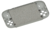
The Playstation 1 has an awesome game library and is super cheap these days-- a great candidate for portablizing! I ordered a couple SCPH-5501s with PU-18 motherboards, which showed up on February 19. The PU-18 mobo looks complicated, but it's only two layers and everything is very low speed.
pu18.jpg


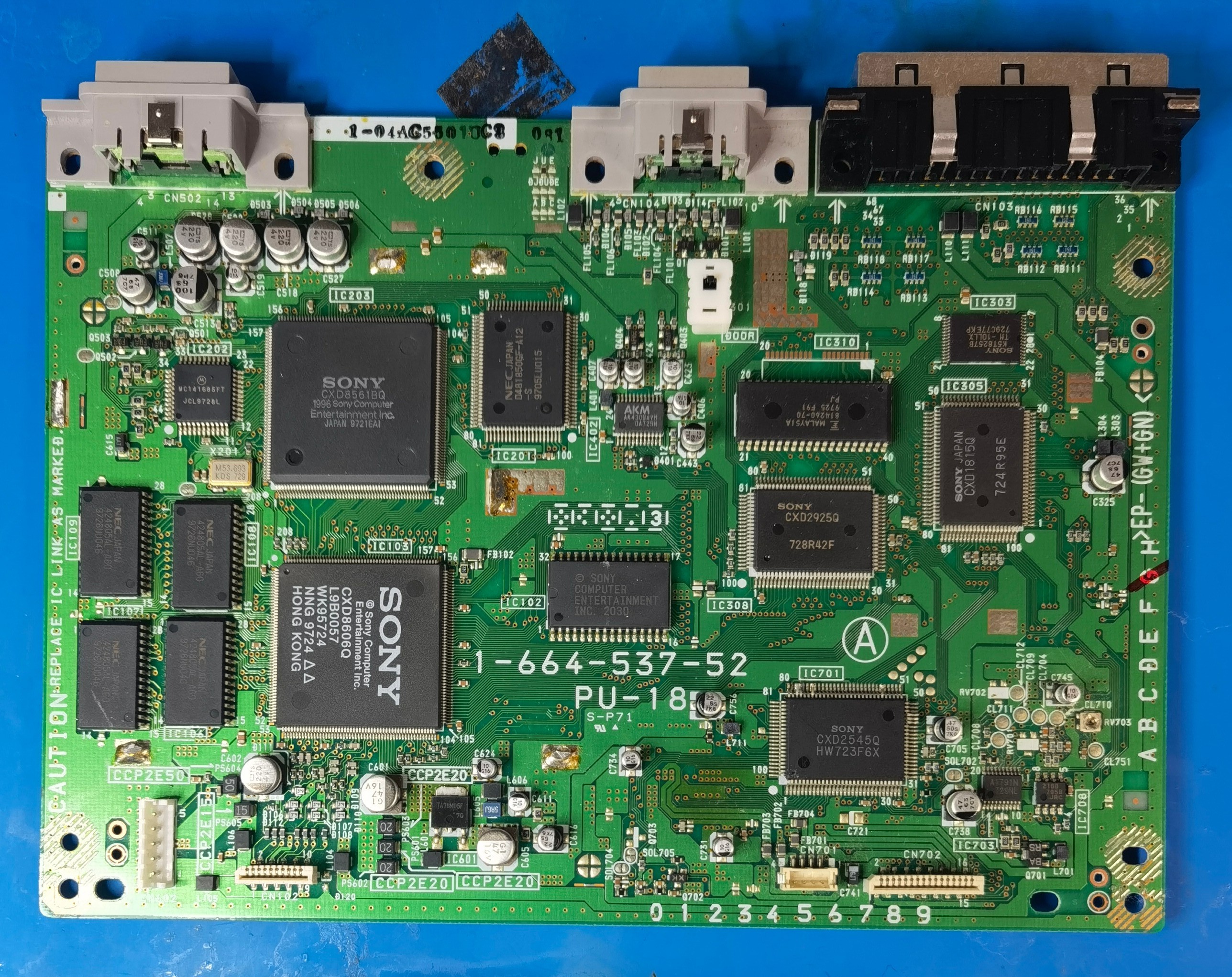
On the left side we have the CPU, GPU and RAM. The right side is all CD drive stuff-- DSP, sub-CPU, mechacon, FIFO, blah blah blah. Right in the middle is the BIOS... it's kinda in the way, isn't it?

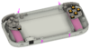
Well, let's relocate it! (February 20)

IMG_20230220_025648.jpg


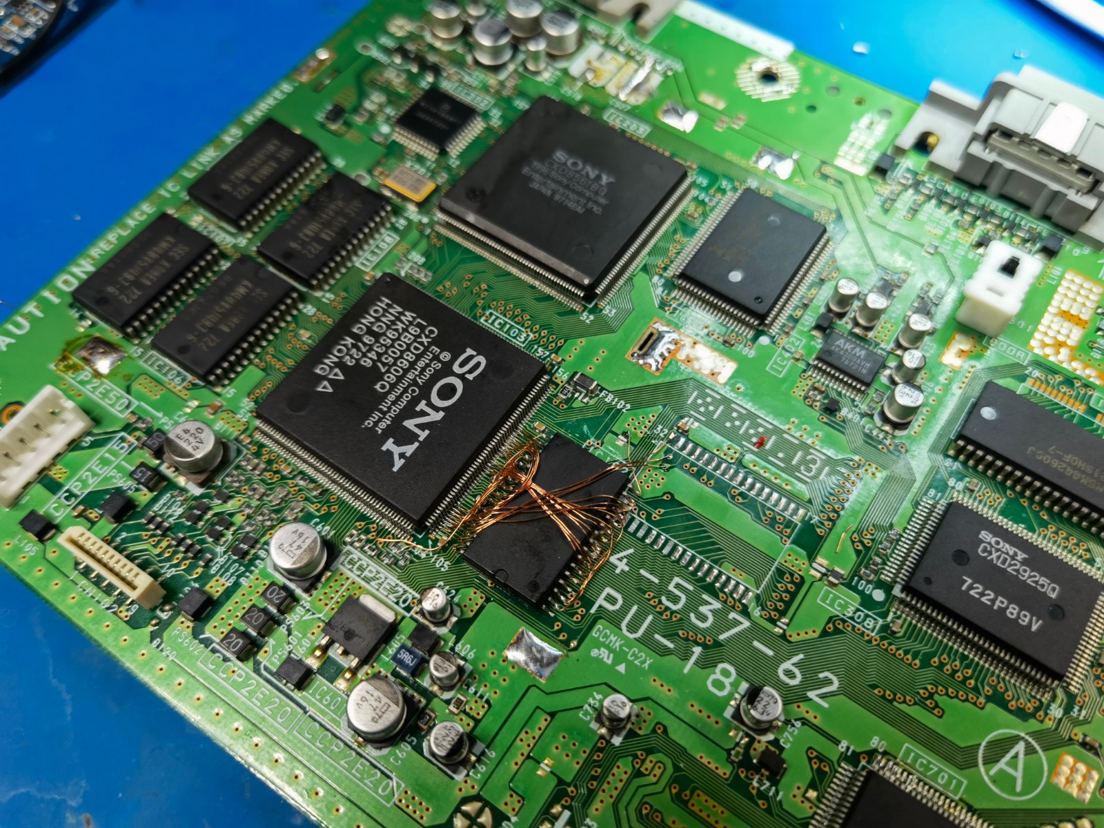
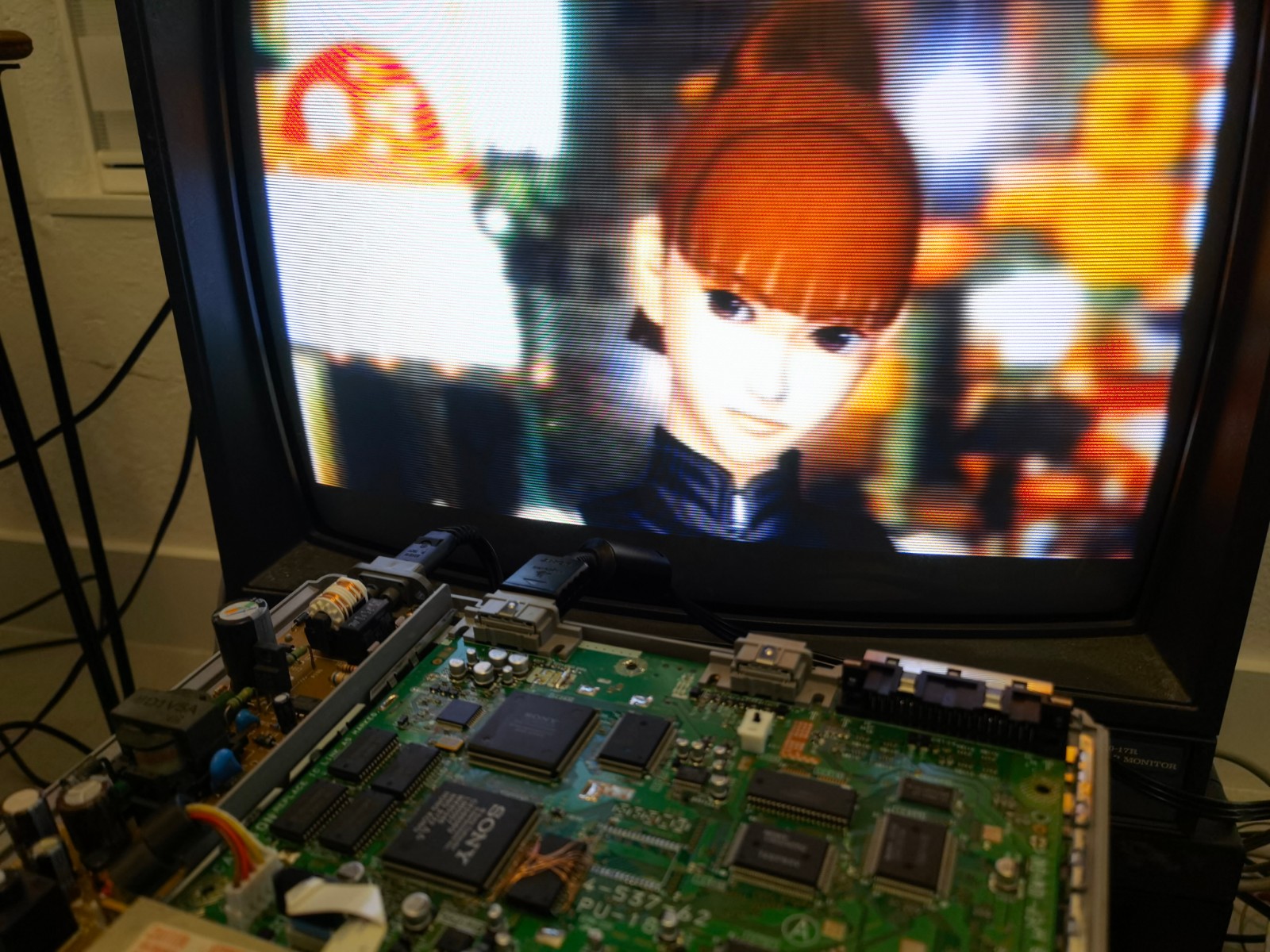
Still works! FYI, if the BIOS isn't connected properly, you won't even get to the white Sony logo screen.

IMG_20230220_030705.jpg


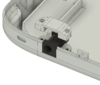
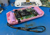
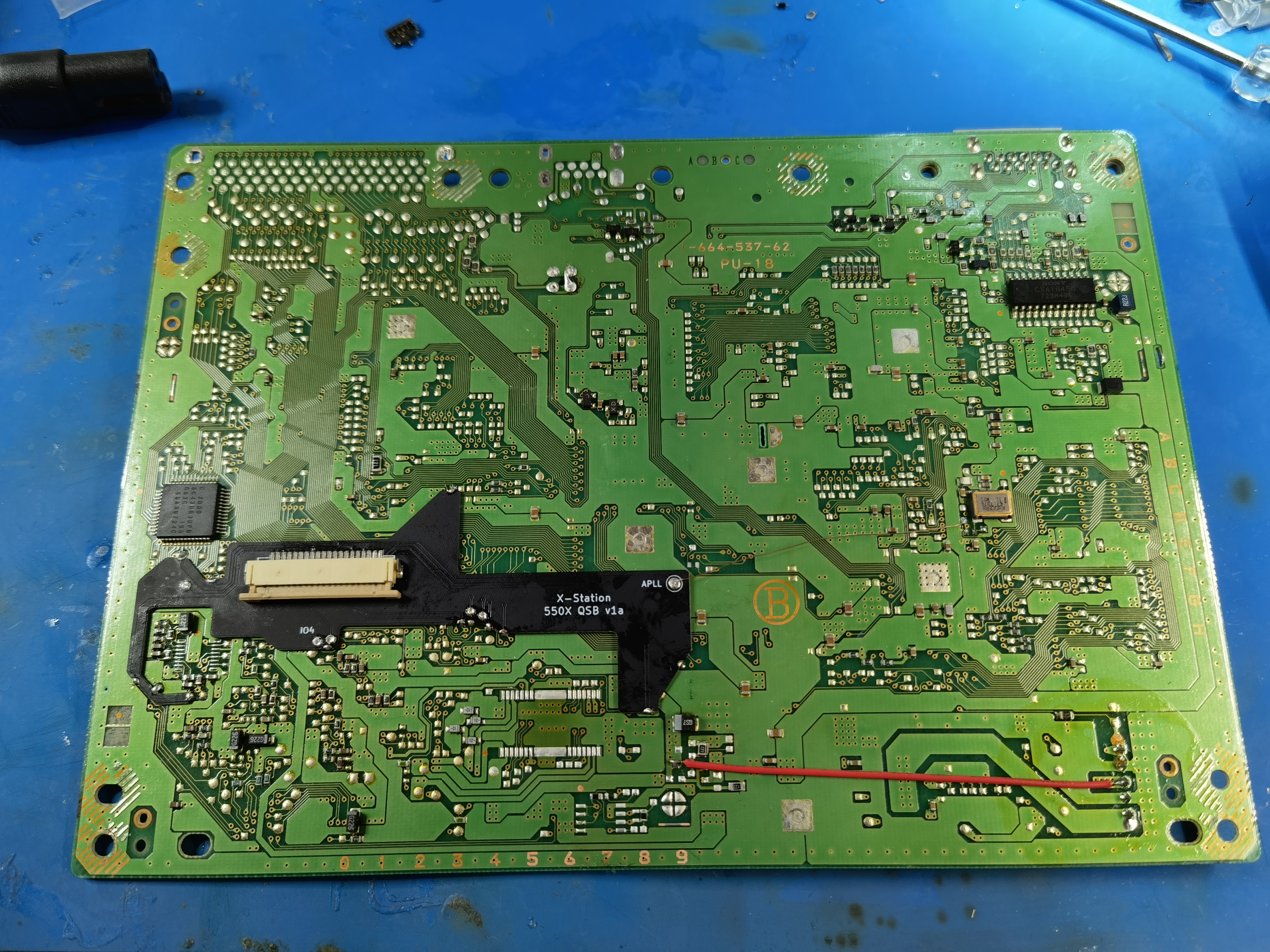
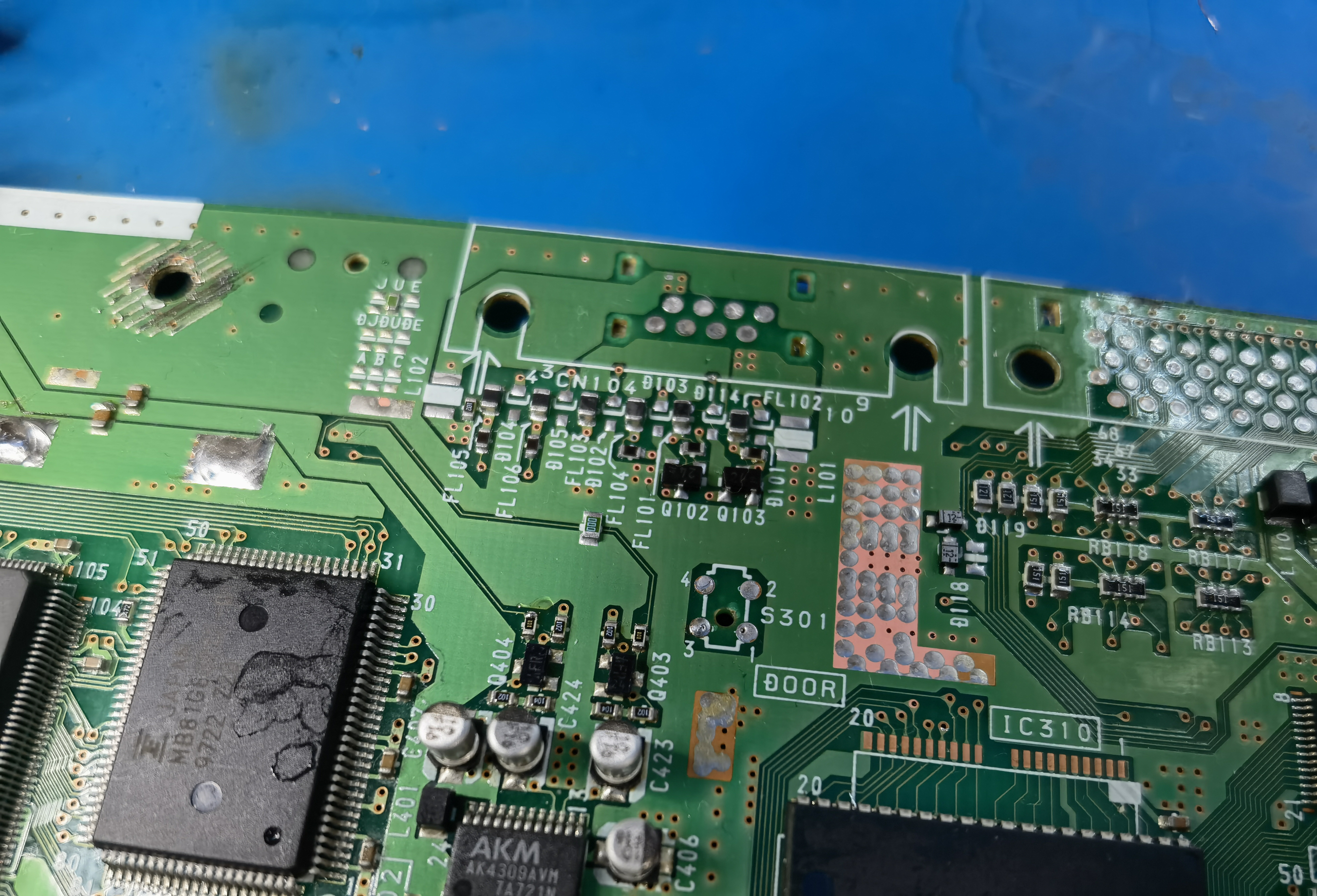
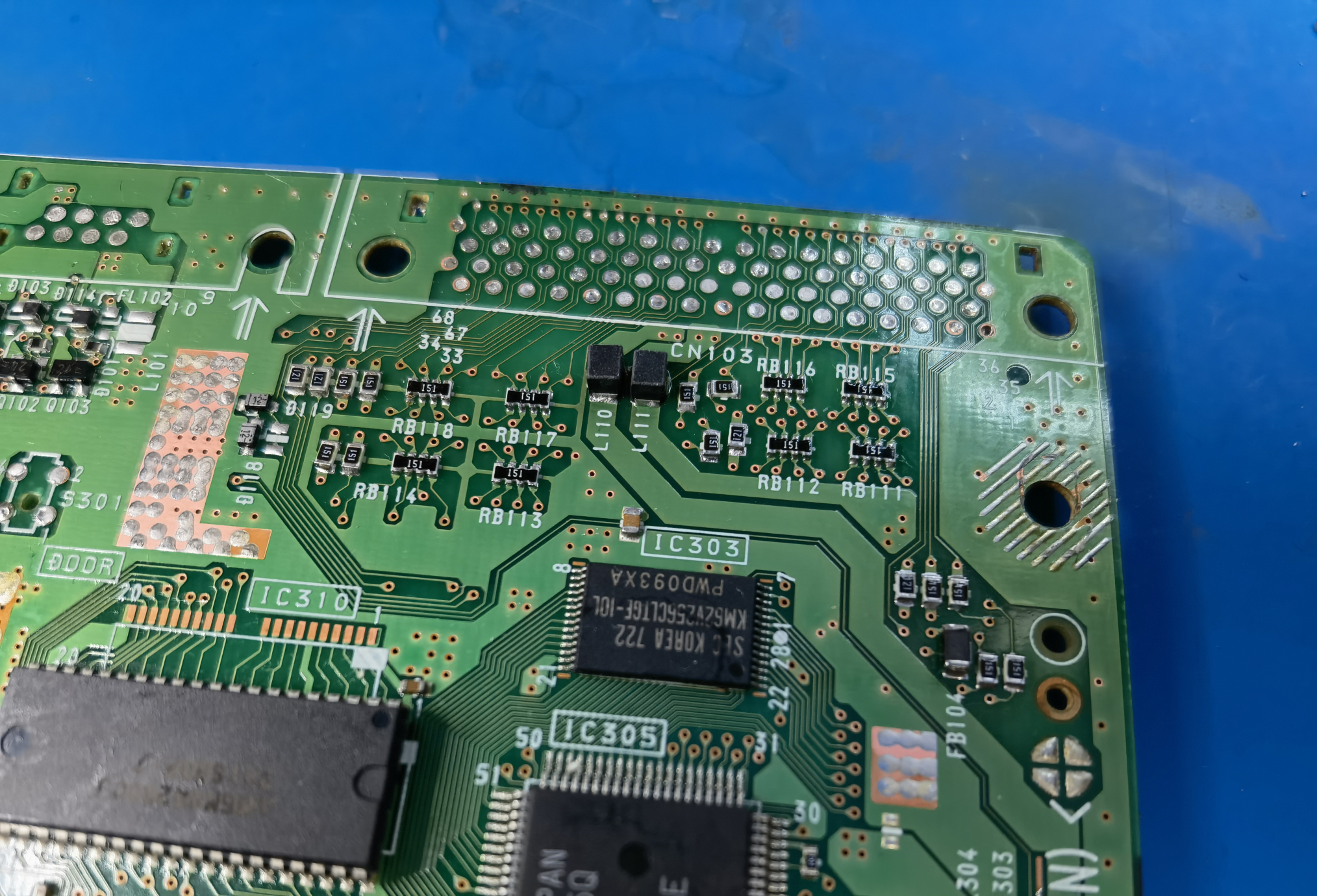
Of course I installed an Xstation for loading games from an SD card. I was able to remove the mechacon and some other nearby ICs through trial and error. Even with Xstation, the sub-CPU and big ICs on the top side are required.

xstation.jpg


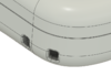
I also removed the serial and parallel connectors. As one does.
IMG_20230225_142507.jpg
IMG_20230225_142505.jpg


Next post... motherboard trimming!
 

YveltalGriffin

First Wii U Trimmer
.
Joined
Jun 7, 2016
Messages
290
Likes
1,044
Location
South Florida
Portables
5
To show you the power of portablizing...
IMG_20230225_144833.jpg

...I cut this board in half!
IMG_20230225_152513.jpg

8y242ubyat011.gif

Taking a page out of @tzmwx 's book on this one! Seriously, thanks for the inspiration, dude. Your Saturn mods are incredible.

Welcome to magnet wire hell! Soldering right to the traces was mandatory due to the relocated BIOS's position. Had to bust out the FM-2032 micro pencil for this.
IMG_20230225_203726.jpg

Side note: I have a terrible habit of overthinking, overengineering, and basically not finishing projects. :blush:

So for this project I did my best to avoid thinking too hard-- just turned off my brain, beeped out the connections with my meter, and soldered. I did consult the PS1 service manuals a few times to check my work, but all the point-to-point wiring was done on the fly with no planning.
IMG_20230225_222948.jpg

IMG_20230225_220642.jpg

I'm used to taping mobos before trimming, but taping afterwards to hold them together...? O.o

IMG_20230226_185207.jpg
IMG_20230225_222846.jpg


Yup, still works! :awesome:
IMG_20230226_123540.jpg
IMG_20230226_160410.jpg


If you're wondering what the point of this trim is, it's to fit the PS1 behind a 5" 640*480 LCD. Yes, you could probably accomplish this by conventionally trimming a PU-22 or PU-23, but those motherboards don't work with Xstation, only PSIO. And PSIO doesn't work with Vib-Ribbon, so that's an obvious non-starter. The lengths I go to for Japanese rhythm games... sheesh.

IMG_20230225_202007.jpg


Next post: the board bend, more antics with magnet wire, and some CAD stuff.
 

StonedEdge

a.k.a. ClonedEdge
.
.
Joined
Nov 16, 2018
Messages
361
Likes
1,473
Location
Japan, Tokyo
Portables
2
72E26469-97BB-44E1-8E44-260C003C6E83.jpeg


Jokes aside, this trim is nuts. TMZXW would be proud of that clean cut and mobo origami!
 

YveltalGriffin

First Wii U Trimmer
.
Joined
Jun 7, 2016
Messages
290
Likes
1,044
Location
South Florida
Portables
5
Well, I'm back from MGC, so I can continue documenting the build process!

On Feb 26 I retrimmed the cut-in-half mobo, removing the top section where the ports used to be.
IMG_20230226_190635.jpg

However, I realized that I hadn't left a wide enough gap between the two mobo halves. There wasn't enough slack in the magnet wire for me fold the mobo in half! Also, the mobo stopped booting consistently, due to some lifted pads under the Xstation QSB. Guess repeated QSB rework is a bit hard on the mobo. ¯\_(ツ)_/¯
IMG_20230304_003318.jpg


So, on March 5 I removed all the magnet wire between the halves and rewired everything much more neatly. While doing so, I inspected the traces more closely and noticed a dozen or so were only routed to the parallel port and therefore not required. Nice!

IMG_20230305_020208.jpg

I also reattached a freshly-trimmed Xstation QSB complete with mag-wire jumpers for the lifted pads.
IMG_20230305_023847.jpg

You might've noticed the initial trim was actually more than a single cut down the middle of the board-- an entire vertical "slice" of the mobo was removed. The audio DAC was on this section, so I had to cut out a DAC daughterboard from a second PU-18. All the electrolytics were replaced with MLCCs to make it low-profile.
IMG_20230226_183345~2.jpg
IMG_20230305_134133.jpg

Audio daughterboard hooked up:
IMG_20230311_185500.jpg

And here's the whole thing blasting some glorious Move Me (Ridge Racer Type 4) over a PAM8803 amp. (The speaker is a leftover sample from work and not an off the shelf part. Sorry!)

I know, I'm spamming pics. But it's just so pretty! :awesome: (That's a sub-CPU chilling on the cardboard. I thought I fried the original with a misplaced wire and swapped in another just to be safe.)
IMG_20230305_152602.jpg


Almost foldin' time! First things first: gotta epoxy that trace-soldering!
IMG_20230309_233447.jpg
IMG_20230309_233524.jpg

I also made sure the board could run on custom regs. The PS1 uses 5V and 3.5V. Here I'm supplying 5V from my bench supply and 3.5V with a PTH08080. (The Xstation's 3.3V LDO is being powered from the 5V rail.) Total system draw is around 3.5W with this setup. Yeah, sneak peek of the case too. I'll get to that. Lots of things were happening in parallel here :P
IMG_20230311_195430.jpg

Next step: remove the Xstation QSB and hand-wire it (March 12). No room for the QSB or a bulky ZIF between the mobo halves! I didn't take a picture showing the Xstation wiring on the backside at this stage, but I have one from a later step I'll post eventually.
IMG_20230312_005305.jpg
IMG_20230312_030725.jpg

Finally-- bend time! Felt like the prep work would never end.
IMG_20230312_142255.jpg
IMG_20230312_141825.jpg

IMG_20230312_141945.jpg
IMG_20230312_141927.jpg

Size comparison with a stock PU-18.
IMG_20230312_142105.jpg

Here it is running! The video has a Dualshock for scale. This post has gotten way too long so I'll pick up on CAD stuff in the next one!
IMG_20230312_143332.jpg


YveltalGriffin

First Wii U Trimmer
.
Joined
Jun 7, 2016
Messages
290
Likes
1,044
Location
South Florida
Portables
5
OK, time to wrap up this retroactive worklog.

I got the case design mostly blocked out by March 6. My primary goal was to minimize the bezels around the 5" 640x480 screen. Pretty happy with the results!

Despite my best efforts I could not fit dual analog sticks AND large front-facing speakers. So no Ape Escape for me...
1686433613237.png

1686433660230.png

1686433522635.png

imag8.png

x2 18650s, orange squishy tacts for all the controls, latching power button, SD card slot.

Dimensions ended up being 181 x 91.5 x 30.25mm. At first I thought the case was too thick, but after doing some quick test prints I found it was insanely comfortable! The controls being placed higher up lets my thumbs rest on them perfectly.
img_20230312_214237.jpg

I continued tweaking the CAD all the way up until the final assembly, right before MGC. Here are some extra pics:
1686411762700.pngimage.png1686412060149.png1686412955020.pngimage-7.png

L1/L2 and R1/R2 are mounted on a 2mm stainless steel rod. The rod is held captive by hollow posts on the front and back halves of the case. This is probably my favorite mechanical aspect of the design!
IMG_20230323_201517.jpg
IMG_20230324_002539.jpg


Once I was happy with the design I printed the final case in white PLA and sanded it. I initially wanted to get the case resin printed and painted the same color as the PSOne (Pantone 7541 U) but PCBWay didn't ship my order in time for MGC.

Here's how the display looked after hooking up a Shinobi Scaler, dialing in the screen settings, and turning on scanlines. The slim bezels and absurdly crisp image really exceeded my expectations. :awesome:

IMG_20230327_010719.jpg

(the dark line on the right side was a GBS Control settings error that I fixed later)
 

YveltalGriffin

First Wii U Trimmer
.
Joined
Jun 7, 2016
Messages
290
Likes
1,044
Location
South Florida
Portables
5
Thanks guys! :D

You might've noticed the thread name changed. Originally I was going to name the portable "PS Hana", since hana (하나) means "one" in Korean. But then @StonedEdge mentioned that hanami parties in Japan were happening for the first time since COVID. And with my Wii portable named "Sakura", well... I just couldn't pass up the chance to keep the theme going. So "PS Hanami" it is!

(I considered doing a two-tone pink and white case, but in the end I preferred the all white look. Still works, since some cherry blossoms are white.)
img_20230319_223756.jpg

Anyway, I realized on March 25 when doing test fits that because of the DC jack placement, I had to retrim the folded motherboard. I also had to trim the Xstation to make room for the SD card slot. It was a bit nerve-wracking to trim the stacked boards, but it went off without a hitch.
IMG_20230325_173622.jpg

IMG_20230325_173355.jpg

I also rewired the audio DAC board to a better spot near the Xstation. Next up was the full-size push-push SD card slot (harvested from a Wii U).
IMG_20230325_182301.jpg

For a one-month speedrun build like this, hot glue was inevitable. I gave in and embraced the jank.

Here's a glimpse inside the PCB sandwich.
IMG_20230327_195045.jpg

Note for those connecting a Shinobi Scaler or screen to the PU-18 RGB lines: C-sync is only present on the motherboard as an input to the video encoder (datasheet). Directly connecting C-sync to something (like a Shinobi) loads the line and results in corrupted video output from the encoder. You might be able to AC-couple into the c-sync line with a series capacitor. But for this portable I used the PS1's luma output as sync instead, and it worked perfectly.

I tore down an official SCPH-110 Dualshock controller and slimmed it down. Even though the unit doesn't have analog sticks, the rumble functionality was still a must-have. Did the same with a red black board by replacing the electrolytic caps with MLCCs.
IMG_20230325_220150.jpg
IMG_20230326_152832.jpg

There was no room for a real memcard slot, and a hardwired one would be too small for more than a couple games. So I soldered up a PicoMemcard+ using a microSD card adapter.
IMG_20230325_214214.jpg

Trying to figure out where to put the red board and Shinobi was a pain in the ass...
IMG_20230325_224658.jpg

In the end, I had to trim the Xstation AGAIN to fit the Shinobi scaler onto the mobo. Ugh!
IMG_20230327_205754.jpg

Periodic test fits were still going well. I think it's hilarious that this portable has both an ESP32 (XStation) and an ESP8266 (Shinobi Scaler). The actual wireless stuff goes totally unused during operation so the side-by-side PCB antennae are kinda ridiculous.
IMG_20230327_214737.jpg

Next I cut up a set of SCPH-110 buttons/d-pad and superglued 3d-printed plates onto the back.
IMG_20230328_012924.jpg
IMG_20230328_012119.jpg

Wired up the controls, red board, latching power button, 5v and 3.5v regs, speakers and audio amp, reset button, disc lid switch... Things got a bit spaghetti, but I like the old school vibes.
IMG_20230328_192129.jpg

I didn't take any internal photos after this point, but before MGC I added a Wiimote rumble motor next to the right battery. The PicoMemcard got wired up later too. The Cutting Edge post will have up-to-date pics of the final internals.

Oh yeah, I intended to have another RP2040 Zero inside the portable to control the power LED, monitor the battery voltage, and change the audio amp volume with button combos. I finished the code, but didn't wire up the Pico in time for MGC. Not a huge deal, it just meant people couldn't adjust the volume and the unit kinda ungracefully shut off once the 2S battery voltage reached ~6V and there wasn't enough headroom for the 5V PTH08080 to maintain a steady output.

On March 28, with just a couple days before MGC, I got the unit all closed up and did some playtesting! Cutting Edge post soon.

Boot + Ridge Racer Type 4 Intro:

Ridge Racer Type 4 music player:
 
Last edited:

Fly_5

.
Joined
Apr 4, 2022
Messages
69
Likes
111
Location
Spain
Portables
Megadrive portable / PS2 Next-G portable
Congratulations on your work.
 
Top