Hi y'all,
I'm starting a new worklog here for a little project I'm doing for fun!
I've been playing my N64 lately and wanted to use the Nintendo 64 controller for Switch because I like the authentic-feeling joystick. I was able to use it on my N64 console wirelessly with a BlueRetro adapter: https://github.com/darthcloud/BlueRetro
But using this adapter, I get some input delay as well as frequent connection drops. Instead of trying to debug BlueRetro I wanted to make my own solution to learn how it all works. I decided to start with USB instead of Bluetooth, though they're really similar under the hood for Switch controllers (both HID).
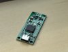
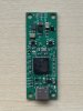
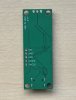
To make this work, I'm using an STM32F401 microcontroller which acts as a USB host to get data from the Switch controller. Then I'll emulate an N64 controller on the same microcontroller and plug it into the console, which should be straightforward since both the console and microcontroller use a 3.3V logic level. Here's the first PCB design and a pic of the controller after I managed to talk to it over USB and light up the LEDs:


Once it's all done I'll post schematics/PCB as well as code for others to use. Hopefully it'll be helpful to someone
I'm starting a new worklog here for a little project I'm doing for fun!
I've been playing my N64 lately and wanted to use the Nintendo 64 controller for Switch because I like the authentic-feeling joystick. I was able to use it on my N64 console wirelessly with a BlueRetro adapter: https://github.com/darthcloud/BlueRetro
But using this adapter, I get some input delay as well as frequent connection drops. Instead of trying to debug BlueRetro I wanted to make my own solution to learn how it all works. I decided to start with USB instead of Bluetooth, though they're really similar under the hood for Switch controllers (both HID).
To make this work, I'm using an STM32F401 microcontroller which acts as a USB host to get data from the Switch controller. Then I'll emulate an N64 controller on the same microcontroller and plug it into the console, which should be straightforward since both the console and microcontroller use a 3.3V logic level. Here's the first PCB design and a pic of the controller after I managed to talk to it over USB and light up the LEDs:
Once it's all done I'll post schematics/PCB as well as code for others to use. Hopefully it'll be helpful to someone
")
 . If anyone knows of a microcontroller that has both USB host functionality and a hardware block that can handle this kind of communication, I'd love to know lol