Worklog First Wii portable attempt No video :(

Stitches

2 and a Half Dollarydoos
Staff member
.
.
Joined
Feb 5, 2017
Messages
3,848
Likes
3,026
Location
Banana Bender Land, Australia
Portables
6
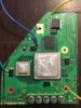
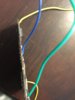
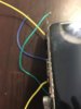
Well, one possibility is your U10 wiring. It looks like the wire might be touching another neighbouring via.
U10.PNG

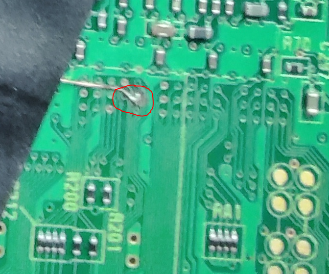
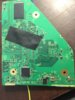
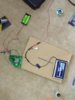
Perhaps try carefully redoing that. Also, could you take the heatsink off the board, put it down on a table or something and take some clearer photos? The ones you've supplied are hella blurry and it's hard to spot potential issues.
 
Joined
Aug 14, 2017
Messages
102
Likes
68
Yeah I think its my phone...kinda sucks but I'll take some clearer ones asap. I'll try to redo that via. Also i was reading through the noob question section and noticed a post stating there's two 3.3v areas of the board. Do I have to run two 3.3 lines?? I currently am only running one. But noticed there's another another above Broadway
 

jefflongo

Broke BitBuilt
Staff member
.
.
Joined
Dec 15, 2016
Messages
1,017
Likes
1,361
Location
Santa Barbara, CA
Portables
3
Yeah I think its my phone...kinda sucks but I'll take some clearer ones asap. I'll try to redo that via. Also i was reading through the noob question section and noticed a post stating there's two 3.3v areas of the board. Do I have to run two 3.3 lines?? I currently am only running one. But noticed there's another another above Broadway
No you do not have to run voltage to both 3.3v lines. They are internally connected (you can verify this by measuring resistance between the two 3.3v locations). You said in an earlier post that you're getting 7.8ohms on 3.3v, .2ohms on 1.15 and 0 ohms on the 1v line? If so that is a major problems. Check the units when you are measuring (did it say 7.8 ohms or 7.8kOhms?). Make sure you're measuring resistance between the voltage line and ground. None of them should be below 10 ohms. If they are, check your wiring and make sure there's no short on the physical wire. If that's not the problem check any other places you have wires. If there's no issues with wires, sand more until the shorts are gone. The trim itself looks fine, but as Stitches said that U10 relocation looks pretty sketchy. I would definitely use a thinner gauge wire, preferably enameled magnet wire.
 
Joined
Aug 14, 2017
Messages
102
Likes
68
I have redone the U10 via its much neater now. I supplied a few pics hopefully clearer. Still the same results unfortunately.. I actually had my multimeter to 200kohms i was reading it wrong..Im getting 8k ohms on the 3.3 line, and about 200 and 600 or so on the 1 and 1.5 lines. So no shorts? I sanded the heck out of the edges. I honestly have no idea what else to do to. I have magnet wire that is the correct gauge on the u10. Ive checked and double checked everything..fml
 

Attachments

Last edited:

Stitches

2 and a Half Dollarydoos
Staff member
.
.
Joined
Feb 5, 2017
Messages
3,848
Likes
3,026
Location
Banana Bender Land, Australia
Portables
6
I have redone the U10 via its much neater now. I supplied a few pics hopefully clearer. Still the same results unfortunately.. I actually had my multimeter to 200kohms i was reading it wrong..Im getting 8k ohms on the 3.3 line, and about 200 and 600 or so on the 1 and 1.5 lines. So no shorts? I sanded the heck out of the edges. I honestly have no idea what else to do to. I have magnet wire that is the correct gauge on the u10. Ive checked and double checked everything..fml
Another possibility could be your 1v wire. It looks a bit spindly and poorly attached, so maybe try desoldering it, strip and tin a fresh length of wire, add some more solder to the 1v spot to make it a bit easier, then resolder the wire. Your other joints seem a bit gloopy, does your iron have a temperature control?
 

BocuD

.
Joined
Jul 21, 2016
Messages
468
Likes
606
Location
The Netherlands
Portables
3
If I have these kinds of issues sometimes just cleaning my entire board with isopropyl alcohol helps. I had boards that would work at all and it would be because there is a drop of solder shorting something out. Also, how did you wire video? Did you connect all of the GND connections? A general rule is that you can never have too much GND.
 

Nold

real emulation, no hardware
Staff member
.
.
2021 1st Place Winner
Joined
Jul 16, 2017
Messages
443
Likes
1,610
Location
EU
Portables
5 + 1*π
I have redone the U10 via its much neater now. I supplied a few pics hopefully clearer. Still the same results unfortunately.. I actually had my multimeter to 200kohms i was reading it wrong..Im getting 8k ohms on the 3.3 line, and about 200 and 600 or so on the 1 and 1.5 lines. So no shorts? I sanded the heck out of the edges. I honestly have no idea what else to do to. I have magnet wire that is the correct gauge on the u10. Ive checked and double checked everything..fml
did you even reconnect reset to ground? from what i see on your pics, you didn't...

Connect the reset via to ground using magnet wire or you'll have to relocate USB, which is more likely to fail then just hard wiring reset... without reset/usb = no video
 
Joined
Aug 14, 2017
Messages
102
Likes
68
I haven't sent updated pics but as of today i do have magnet wire connected from the reset via to ground my voltages are correct after redoing my regulators, while under load, connected to the board. I have my regulators all linked to ground on my board also i have a composite screen the yellow composite cable i have stripped and the ground is going to the board the yellow video cable attached to the last capacitor on the board on the right according to the trim guide. I tested the screen with the Wii prior to the trim everything worked fine im thinking it has to be the u-10 or shorts on the board still but I'm getting good readings for ohms so i didn't think it was shorted..i can wipe the whole board down with ipa maybe there's some metal dust stuck somewhere shorting it....I can redo the 1v line also and see if that works..I didn't think my soldering was an issue because I'm getting good voltage readings on other parts of the voltage lines on the board.
 
Joined
Aug 14, 2017
Messages
102
Likes
68
If I absolutely can't get either of my boards to turn on would anyone be willing to give it a shot? I'll mail them to you and if you can get it to work I'll pay you to mail me them back. I know its frowned upon in this community and I'll prob. Not get any takers but it couldn't hurt to ask. I'm obviously doing something wrong if both boards have the same result and am about to give up. Sucks because I already have a pretty cool case ive been modeling and bought most of the materials needed already. Just cant get past this step.
 

jefflongo

Broke BitBuilt
Staff member
.
.
Joined
Dec 15, 2016
Messages
1,017
Likes
1,361
Location
Santa Barbara, CA
Portables
3
This should be your troubleshooting plan:
- check the output of the regulators when NOT connected to the board
- check resistances on the voltage lines with no regs attached
- connect regs and check output when with is powered on make sure they aren't too low
- check output of U10 make sure it reads 3.3v, also make sure the input pin has continuity with 3.3v and the group of 3 pins has continuity with ground

you'll get it eventually dude
 
Joined
Aug 14, 2017
Messages
102
Likes
68
I'll try all of that. I actually don't think I have been getting a volt reading on my U-10. Maybe it isn't soldered correctly or I didn't cut the trace well enough. Thanks a lot for everyones help. I'm going to keep at it and hopefully get this thing to work
 

jefflongo

Broke BitBuilt
Staff member
.
.
Joined
Dec 15, 2016
Messages
1,017
Likes
1,361
Location
Santa Barbara, CA
Portables
3
Joined
Aug 14, 2017
Messages
102
Likes
68
Honestly I'm not too sure. I cleaned up the edges more and soldered pin 5 I believe of the U10 a little better. I re-soldered my 1v connection on the board. I also wiped the whole thing down with isopropyl alcohol. I guess one or a combination of those things did the trick.
 
Top