
Correct, removing either would accomplish the same task. Whatever's easier.
Worklog Can someone help check my work
- Thread starter Gabobo
- Start date
Gabobo
.
- Joined
- Jan 28, 2020
- Messages
- 62
- Likes
- 20
Well. It was just one thing. This is a big deal to me. I spent all night looking up chips and learning all about resistors and it was really just an inductor. Now I know that the screen works and I'm a happy camper. Also jefflongo. The guide I was thinking of ended up being in the guide hub. I thought it was a work log this while time. Thanks.
Attachments
-
 3 MB Views: 256
Gabobo
.
- Joined
- Jan 28, 2020
- Messages
- 62
- Likes
- 20
I'm going to work on the GC+ and the controls now. All I need are data cables right? I'm either going to use the 28 gauge or the 34 gauge.
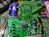
Like the title suggests, can someone check my work so far? Waiting for a new PMS is going to take awhile and I'm obviously going to shorten the cables, but I just need to know if I would need to fix something or if there is a better place to wire something else. No rush this time. For real.
Like the title suggests, can someone check my work so far? Waiting for a new PMS is going to take awhile and I'm obviously going to shorten the cables, but I just need to know if I would need to fix something or if there is a better place to wire something else. No rush this time. For real.
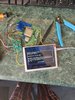
Attachments
-
 5.7 MB Views: 264
Correct, the connections from the GC+ to the controls can use 34AWG no problem. As for your other wires, everything looks like it should be okay to my eye. Just keep an eye on the USB data wires, they're easy to accidentally break off if they catch on something.I'm going to work on the GC+ and the controls now. All I need are data cables right? I'm either going to use the 28 gauge or the 34 gauge.
Like the title suggests, can someone check my work so far? Waiting for a new PMS is going to take awhile and I'm obviously going to shorten the cables, but I just need to know if I would need to fix something or if there is a better place to wire something else. No rush this time. For real. View attachment 11104
Yes this is correctWithout going to details... How do you guys normally wire your batteries? B+ is the smaller circle side and B- is the flat one, but B- is connected GND on the PMS right?
Gabobo
.
- Joined
- Jan 28, 2020
- Messages
- 62
- Likes
- 20
Thank you very much. I was thinking about whether to hook them up either series or parallel. I was looking through work logs and most of them have a little part of the battery obscured so I wanted to know how you people do it.... so I don't fry another PMS...
The RVL PMS from the store only supports a 1s configuration. That is, all batteries should be in parallel. By the way, if you're ever unsure of the polarity of something, you can simply measure the voltage with a multimeter to confirm which end is positive and which end is negative.
Gabobo
.
- Joined
- Jan 28, 2020
- Messages
- 62
- Likes
- 20
Yes... Parallel... Thank you for confirming that... That's where the B+ are all connected with each other and all the B- are also connected with each other to extend the capacity but keep the same voltage. It makes sense now that my second PMS is dead. Just to also confirm, series is when voltage increases but capacity stays the same, yes?
CorrectYes... Parallel... Thank you for confirming that... That's where the B+ are all connected with each other and all the B- are also connected with each other to extend the capacity but keep the same voltage. It makes sense now that my second PMS is dead. Just to also confirm, series is when voltage increases but capacity stays the same, yes?
Gabobo
.
- Joined
- Jan 28, 2020
- Messages
- 62
- Likes
- 20
Putting up U-Amp and GC+ in the downtime. Would connecting all the GND wires from all the button and turning them into one gigantic super wire do bad things to the wii? Of course, connected to the GND on the wii.
Now the U-Amp questions, if I DO NOT want i2c/sexy audio I would connect exactly which pins? I'm guessing just the L/R+/-, the 3.3v, GND, +/- tact control, LR and LL, and bridge J0. Not trying to kill more things but I can no longer trust my brains.
Now the U-Amp questions, if I DO NOT want i2c/sexy audio I would connect exactly which pins? I'm guessing just the L/R+/-, the 3.3v, GND, +/- tact control, LR and LL, and bridge J0. Not trying to kill more things but I can no longer trust my brains.
Gabobo
.
- Joined
- Jan 28, 2020
- Messages
- 62
- Likes
- 20
I'm actually stuck this time. Lots of things happened and going through a whole adventure I had many problems and fixes to those problems but right now I have a problem that needs a little direction. So I can confirm that the wii somehow worked before, Bluetooth and all, but when suddenly it stopped working. Here's the thing, The resistance for the 3.3v and 1v are at the correct range when the battery is disconnected, that being 8-ish Ohms and 220 ohm respectively. But when I hook up the battery, the resistances are down to 160ohms and 100 ohms. When I remove the battery, it goes back to normal.
Also I have another display problem. Story is: Messed up my 4:3 Screen. Turns out the brightness cable just needed to reflow it's solder, cracked screen in celebration. I had an eyoyo 5inch screen as backup. I just want YPbPr but the screen board is the NEW eyoyo October 25 2019 revision and following some google image of Component to VGA, I HAD the screen displaying in Black and white, before the mysterious resistance drop. Now Bluetooth aint working but I can feel the heat from the CPU and GPU. I put the heatsink on to test so the thing doesn't die on me. My conclusion is that it's turning on BUT since screen and bluetooth do not work, I believe it's stuck in limbo. I hooked up the analog from the Uamp to the wii but no sound comes out and I do not think the wii is completely powered on.
Also soldered USB data pins to it's Pin 6 and 7 vias, I don't know if that has to do with anything.
Any thoughts?
8? Sounds kinda low to me... Anyway, don't try to measure resistance on a powered circuit, it won't read right.that being 8-ish Ohms
Got pics of the board? That would help us identify what could be wrong
Gabobo
.
- Joined
- Jan 28, 2020
- Messages
- 62
- Likes
- 20
I meant 8k ohms,as in big ohms, but never mind that. This worked before. Somehow. I believe we are in different time zones so give me a sec to remove some wires.
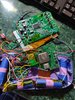
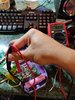
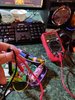
Edit: removed some wires to the Uamp as they just got in the way. Also to add more info. The Wii was working perfectly fine before when connected to the PMS using 24 gauge wires. I've tried my 22 gauge but same problem. This problem started when it was one battery. I put all 4 batteries in parallel but same problem. When powered on Volts read the correct voltage (3.3v shows exactly 3.3, 1v shows 1).
Edit: removed some wires to the Uamp as they just got in the way. Also to add more info. The Wii was working perfectly fine before when connected to the PMS using 24 gauge wires. I've tried my 22 gauge but same problem. This problem started when it was one battery. I put all 4 batteries in parallel but same problem. When powered on Volts read the correct voltage (3.3v shows exactly 3.3, 1v shows 1).
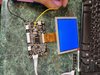
Attachments
-
 6.7 MB Views: 229
 -
 6 MB Views: 226
 -
 6.1 MB Views: 209
 -
 5.5 MB Views: 214
Last edited:
Gabobo
.
- Joined
- Jan 28, 2020
- Messages
- 62
- Likes
- 20
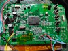
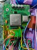
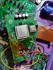
This is my supervillain origin story. I cleaned up the board, backtracked to the point where I lost Bluetooth, switched to 22 Awg wire. I don't know anymore. Reflowed the joints, resoldered and resoldered the joints, charged the batteries. I don't know what's happening anymore. Now I know 3.3v shouldn't drop it's resistances from 8.6k Ohms to 160 ohms just from hooking up the batteries. Let's see if this helps identify there problem.
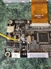
Attachments
-
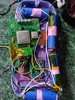
 4.2 MB Views: 209
 -
 5.4 MB Views: 200
 -
 5.6 MB Views: 201
 -
 6.3 MB Views: 196
Also, just making sure, are you giving this screen component or VGA video? If it's VGA, you need the hsync and vsync wired as welldon't try to measure resistance on a powered circuit, it won't read right.
Last edited:
Gabobo
.
- Joined
- Jan 28, 2020
- Messages
- 62
- Likes
- 20
Nope. Didn't install the patches on this cursed wii. Just using Component cause I composite ain't working right and YPbPr was the only thing giving me any sort of progress. It was in black and white. Also I going to assume that the power is fine but the bluetooth dying out of nowhere has me concerned. I also "tried" VGA with the hsync and vsync by connecting them from the chip itself but removed them so I could troubleshoot this easier.
Ah, uh, I'm a little confused now as to what isn't working 
So have you tested your screen with another video source to make sure it's still working and on the correct input?
If so, does the Wii give a black screen, no video, or does it show something with postloader?
So have you tested your screen with another video source to make sure it's still working and on the correct input?
If so, does the Wii give a black screen, no video, or does it show something with postloader?
- If it is no video, double check U10 and all the voltages when it is on.
- If it is black screen (some kind of video is coming out but it's just black), hold reset to ground to see if you get the priiloader menu.
- If it is something with postloader, check your USB wiring, and make sure it is twisted tightly (can't quite tell from the pictures, they're a bit too blurry)
Gabobo
.
- Joined
- Jan 28, 2020
- Messages
- 62
- Likes
- 20
Cause this was before the video also died. There's no video, no bluetooth, and voltages all read normal. Checked U10 and that's at 3.3v. I'm also confused. Hooked up analog audio and closed both jumpers and ended up getting no sound when powering on. Portablizemii has a very distinct start up sound and no sound comes out. I'll try hooking up the GC+ so I can press A? I'll report back and see how that goes.