
Worklog Can someone help check my work
- Thread starter Gabobo
- Start date
Gabobo
.
- Joined
- Jan 28, 2020
- Messages
- 62
- Likes
- 20
Have to report, Got the GC+ on the wii. Pressed A. Nothing. Can't get composite because I don't know which AV pin/hole to solder to on the screen itself. I think the wii itself just refuses to boot. I say that because analog UAmp is hooked up with no startup sound, no video displays and even if it did, bluetooth is not connecting to my wiimote. Voltages are fine so I guess something is weird with my Wii itself. Could it be my batteries are weird because I can't think of anything anymore.
Gabobo
.
- Joined
- Jan 28, 2020
- Messages
- 62
- Likes
- 20
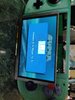
I concluded that the Wii fugging died. New Wii. Found the composite pin. Took like a total of two seconds to get it running. Thanks for trying Cheese. I think it was the CPU. I see some melted garbage in between the crack but I have nothing sharp enough to clean it out. It was also cursed. PortabilizeMii didn't install without the MMM fix, 1.15v died and had to be reflowed, composite pad fell off, etc. This Wii, two hours from installation to trimming to this. I'm exhausted. Goodnight
Gabobo
.
- Joined
- Jan 28, 2020
- Messages
- 62
- Likes
- 20
Jesus Christ. Anyone that's new to this, I encourage you to read through the entire trimming guide at least nine times before starting, including the software part. Forgot to install Bootmii as IOS and now the wii don't read wii games. Hackmii Installer does not go past the scam screen with the nowifi Patched IOS. Made a cute little sync and reset buttons in the process. Went around it by using USB Loader GX but that's not the Portablize Mii experience is it?
Question, how would I go about trying to install BootMii now? My only chance would be to revert IOS58 and run HackMii again (just like the good old days) but I'm scared that'll mess up my Wii because it brings back the WiFi requirement.
Question, how would I go about trying to install BootMii now? My only chance would be to revert IOS58 and run HackMii again (just like the good old days) but I'm scared that'll mess up my Wii because it brings back the WiFi requirement.
IIRC you can wire wifi and the SD slot in, and just rerun hackmii for bootmii and cheese installer for nowifi. Then you can desolder wifi and the SD slot. It's annoying to do, but I think that's the only way. Unless the Pizza Wizard himself has a special IOS module you can install via MMM (which I doubt, but maybe).Jesus Christ. Anyone that's new to this, I encourage you to read through the entire trimming guide at least nine times before starting, including the software part. Forgot to install Bootmii as IOS and now the wii don't read wii games. Hackmii Installer does not go past the scam screen with the nowifi Patched IOS. Made a cute little sync and reset buttons in the process. Went around it by using USB Loader GX but that's not the Portablize Mii experience is it?
Question, how would I go about trying to install BootMii now? My only chance would be to revert IOS58 and run HackMii again (just like the good old days) but I'm scared that'll mess up my Wii because it brings back the WiFi requirement.
How did you get USB loader gx working? That requires the disc drive daughterboard... Anyway, you should be able to just install bootmii ios from a wad, though I don't have one. Don't try to wire wifi, it will be a nightmare at best
Gabobo
.
- Joined
- Jan 28, 2020
- Messages
- 62
- Likes
- 20
Sorry my bad, I clicked Resident Evil 2 instead of Super Mario Galaxy. I'm going to try the Cheese Method first cause that sounds easier and I think I have that from my boomer softmodding days somewhere. I'm not about to cut more traces for that SD card and those wifi legs are TINY bro. Unfortunately, if this doesn't work, I'll just have to wait for Magic Pizza Man to grace us with some miracle healing software. I'll use the edit button to report back my results. Next post should be the final one, hopefully.
EDIT: Oh my God. Please let my mistakes be known! The trick is to lurk discord and use their search button. Magic pizza man said to use MMM and load IOS80 to install wads. Install from neek/emunand again. Bootmii IOS was found by cross referencing it's base IOS which is 254 and accidentally coming across a GitHub that had it for a project. It was the same one I had from a backup I had 8 years ago and I used it to make sure newcomers know that it works. My God. It's almost done. I just need to quickly learn how to CAD so this screen fits this case, clean up the GC+ wires, get YPbPr up and get better audio. Thanks guys. No need to wire up WiFi and SD.
EDIT: Oh my God. Please let my mistakes be known! The trick is to lurk discord and use their search button. Magic pizza man said to use MMM and load IOS80 to install wads. Install from neek/emunand again. Bootmii IOS was found by cross referencing it's base IOS which is 254 and accidentally coming across a GitHub that had it for a project. It was the same one I had from a backup I had 8 years ago and I used it to make sure newcomers know that it works. My God. It's almost done. I just need to quickly learn how to CAD so this screen fits this case, clean up the GC+ wires, get YPbPr up and get better audio. Thanks guys. No need to wire up WiFi and SD.
Last edited:
Gabobo
.
- Joined
- Jan 28, 2020
- Messages
- 62
- Likes
- 20
Well I kept my word. Last post, I closed it. I'm not going to show my spaghetti. That's something I'll do better next time. It was only there because I jumped the gun on wiring the GC+ without getting all the pieces together and I refused to measure wires. That's my bad.
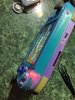
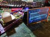
Here it is. I didn't work on sanding or anything because the amateur doofy look gives it an almost crayon feel. I had to go with the G-Wii but I also broke MANY things along the way. The screen broke and I resorted to using my spare Eyoyo Component screen but it also completely screwed me over because that was not a 4:3 screen and I had to print out another top as well as another bottom because the trigger stand broke on me (Don't skimp on the slicer settings new people.) Gotta thank Wesk in discord for making it, even if I lurked in the search bar to look for a solution. I also added a jewel CD case with double sided tape for future protection in case anything tries to break my very expensive screen. The screen is the scariest part to break as of now because of the ongoing pandemic, and international shipping ain't working and China can't deliver on time!
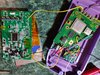
I also ripped off the solder pad from the U-Amp 3.3v and bit the bullet and asked on Discord. Thanks Noah for the diagram but it didn't work AT FIRST because it turns out, that tiny little via has to be a part of the line as well and I ripped off waaaaay more than the pad.
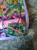
I got that sorted out but then the video started messing up on me as well! and I had to find out why the Y line wasn't getting signal and when it did, the Pb was also not getting signal!
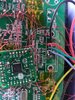
The pads broke and tore apart the data lines so I used that U-Amp knowledge and found the data traces! That blob right there is the only thing connecting my wire to the Pb data, and I secured that with Kapton tape. Thank god for Kapton tape.
I had to learn many things throughout this entire project but the one thing that stands out the most is how important a multimeter is at the endgame of this project. I always thought it was optional and because of that I didn't learn how to read one until the U-Amp fiasco. learned how to read resistances and voltages like a boss. Thanks to Cheese for that one.
I fried three PMS (PARALLEL CONNECTIONS. '+' touch only '+' and '-' touch only '-'!!!" and three Wii ( I made sure the first two were completely fried so I wouldn't look back). I am completely sure I got metal in it from sanding in the third wii, killing it entirely when it melted into solder globs. Gotta tape up those CPU/GPU when sanding. Also Jefflongo's little daisy chaining trick with the Bluetooth works for basically everything that needs those lines. I daisy chained the Mode pad to the Bluetooth which is also connected to the fan and the U-Amp. I know better now but it was funny to see one thing jumping to another until the whole thing works. I actually used that trick to get my Vol + and Vol - to work with the menu controls. Still works...
I was also going to show off some battery holders that I made from nickel strips which is held together by hot glue and pressure but uploading is weird and I may have to edit this post. Basically, I wanted to have a way to replace the batteries without soldering and I got it to work! Kapton tape and Hot glue baby! It doesn't even short from the trigger buttons.
I referred to Stitches' Eyoyo guide (Thanks BTW) for the Component (YPbPr) to VGA connections but I don't know how relevant this is, the newer model fixes the RGB placement and has it exactly where it shout be for component (YPbPr). I also didn't have to remove anything to get the screen powered on! Wire goes to the same looking components from Stitches guide, just please use a multimeter to check which one is not Ground.
One final thing, reflow solder for weird connections (whoever this applies to.) I had to reflow the 1.15v line because the flux I used got cat hair stuck underneath, which shorted the line to Ground, confusing me for days. This is the same Wii that died from sand. Also if you see that my GC+ 1.0 magically changed to 2.0, that's because I found out during testing that there is no real solution to dual tacts for the 1.0 and I had to do some component swap/removing that ended up taking way more time than just using the 2.0 that was lying around... It was a 5 minute job moving wires from one to another.
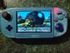
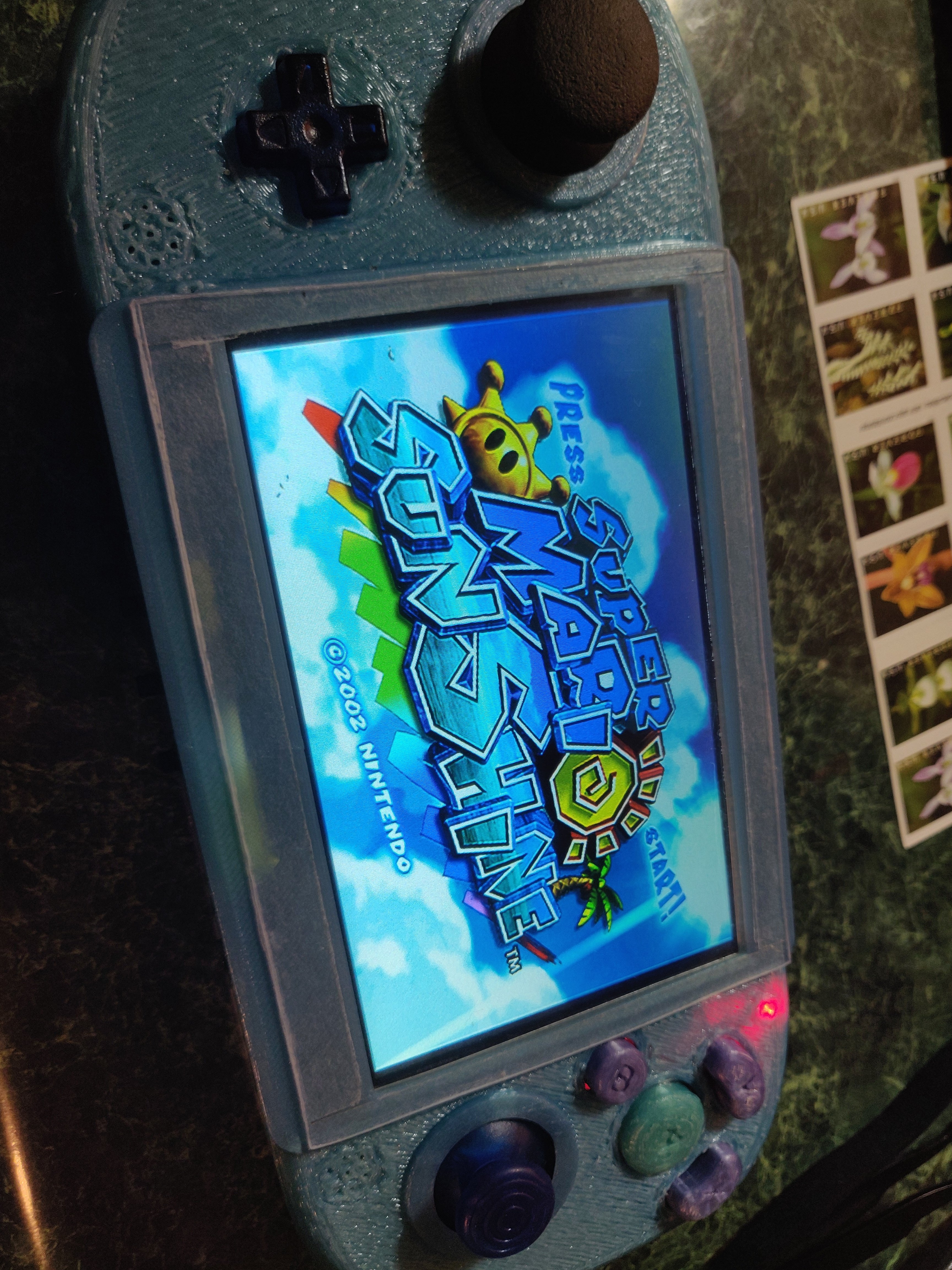
I really have to thank everyone who stuck around for this journey. Y'all checked my work until I got things going and made me feel like I can actually do this. This is actually my second DIY project involving electronics and I'm really happy how this came out. It's not super fancy like some of the ones I see here but it's mine and I'm really having fun playing Mario Sunshine on my toilet (This was my dream 10 years ago). If I didn't mention you and you helped out, thank you for being around, I just want to sleep right now.
Here it is. I didn't work on sanding or anything because the amateur doofy look gives it an almost crayon feel. I had to go with the G-Wii but I also broke MANY things along the way. The screen broke and I resorted to using my spare Eyoyo Component screen but it also completely screwed me over because that was not a 4:3 screen and I had to print out another top as well as another bottom because the trigger stand broke on me (Don't skimp on the slicer settings new people.) Gotta thank Wesk in discord for making it, even if I lurked in the search bar to look for a solution. I also added a jewel CD case with double sided tape for future protection in case anything tries to break my very expensive screen. The screen is the scariest part to break as of now because of the ongoing pandemic, and international shipping ain't working and China can't deliver on time!
I also ripped off the solder pad from the U-Amp 3.3v and bit the bullet and asked on Discord. Thanks Noah for the diagram but it didn't work AT FIRST because it turns out, that tiny little via has to be a part of the line as well and I ripped off waaaaay more than the pad.
I got that sorted out but then the video started messing up on me as well! and I had to find out why the Y line wasn't getting signal and when it did, the Pb was also not getting signal!
The pads broke and tore apart the data lines so I used that U-Amp knowledge and found the data traces! That blob right there is the only thing connecting my wire to the Pb data, and I secured that with Kapton tape. Thank god for Kapton tape.
I had to learn many things throughout this entire project but the one thing that stands out the most is how important a multimeter is at the endgame of this project. I always thought it was optional and because of that I didn't learn how to read one until the U-Amp fiasco. learned how to read resistances and voltages like a boss. Thanks to Cheese for that one.
I fried three PMS (PARALLEL CONNECTIONS. '+' touch only '+' and '-' touch only '-'!!!" and three Wii ( I made sure the first two were completely fried so I wouldn't look back). I am completely sure I got metal in it from sanding in the third wii, killing it entirely when it melted into solder globs. Gotta tape up those CPU/GPU when sanding. Also Jefflongo's little daisy chaining trick with the Bluetooth works for basically everything that needs those lines. I daisy chained the Mode pad to the Bluetooth which is also connected to the fan and the U-Amp. I know better now but it was funny to see one thing jumping to another until the whole thing works. I actually used that trick to get my Vol + and Vol - to work with the menu controls. Still works...
I was also going to show off some battery holders that I made from nickel strips which is held together by hot glue and pressure but uploading is weird and I may have to edit this post. Basically, I wanted to have a way to replace the batteries without soldering and I got it to work! Kapton tape and Hot glue baby! It doesn't even short from the trigger buttons.
I referred to Stitches' Eyoyo guide (Thanks BTW) for the Component (YPbPr) to VGA connections but I don't know how relevant this is, the newer model fixes the RGB placement and has it exactly where it shout be for component (YPbPr). I also didn't have to remove anything to get the screen powered on! Wire goes to the same looking components from Stitches guide, just please use a multimeter to check which one is not Ground.
One final thing, reflow solder for weird connections (whoever this applies to.) I had to reflow the 1.15v line because the flux I used got cat hair stuck underneath, which shorted the line to Ground, confusing me for days. This is the same Wii that died from sand. Also if you see that my GC+ 1.0 magically changed to 2.0, that's because I found out during testing that there is no real solution to dual tacts for the 1.0 and I had to do some component swap/removing that ended up taking way more time than just using the 2.0 that was lying around... It was a 5 minute job moving wires from one to another.
I really have to thank everyone who stuck around for this journey. Y'all checked my work until I got things going and made me feel like I can actually do this. This is actually my second DIY project involving electronics and I'm really happy how this came out. It's not super fancy like some of the ones I see here but it's mine and I'm really having fun playing Mario Sunshine on my toilet (This was my dream 10 years ago). If I didn't mention you and you helped out, thank you for being around, I just want to sleep right now.
I think most of us when we were first starting experienced something similar to what you went through. It can be really tempting to give up when everything starts going wrong, especially close to the eclipse of the project. You may not be proud of every aspect of your portable, but you finished it and that took a lot of patience and perseverance. There's a lot to be said for that. Debugging is often the lowest part of a project but the experience you get coming out of it is invaluable. I think you'll be surprised of what you'll be capable of making for your next project as a result of this experience. Great work!
mokus
.
- Joined
- Apr 12, 2020
- Messages
- 23
- Likes
- 76
Totally agree with @jefflongo - persevering and finishing is success! All the people doing super awesome work on this forum started somewhere, and the reason they got where they are now is by just keeping it up. The difference between a pro and an amateur is that the pro has made so many frustrating mistakes they now know how to recover quickly and gracefully when they make more ")
So true - Kapton tape is the duct tape of the electronics world!Thank god for Kapton tape.