N64HH V2

Joined
Sep 8, 2019
Messages
208
Likes
519
Location
Louisiana
Portables
2
N64HH-V2-12-27-2023.jpeg

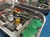
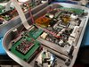
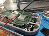
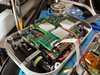
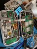
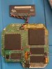
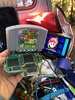
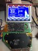
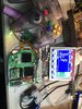
The N64HH Rev2! Improved and better than ever!

IMG_2130.jpeg
IMG_2129.jpeg

IMG_2127.jpeg
IMG_2125.jpeg

Improved the trigger design, used FFC cable to make wire routing simpler, custom made PCBs, and passive cooling setup!
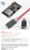
Uses
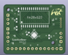
Advanced Trim N64 motherboard with direct RCP wiring
5 inch 4:3 screen
Gman’s RVL-PMS (could use another with modification to MB bracket)
Gman’s 64Amp (open source)
Sparklebear’s Sparkleboard (closed source) with Gman’s joy on stick to N64 stick coding.
CrazyGadget’s OSD controller (used for volume control)
2x 18650 batteries
Original rubber membranes (cut with scissors to separate AB and CPAD)


Build your own!

I plan on maybe making an YouTube video talking about to to put it together and what parts are needed.

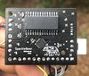
ORDERING MY PCB CONTACT BOARDS:
I’d recommend getting the pcb boards ENIG gold plated for maximum sensitivity!

BOM (In progress)


Current difficulties building your own:
The pcb used as the N64 controller (Sparkleboard 64) is closed source, so someone (or me) would need to make a custom pcb to mount the N64 controller chip and a pic microcontrolller to use Gman’s open source Joycon Stick to N64 Stick code.

Also side note, this will be the final revision for a while, I am very satisfied with this current design. Therefore, If you plan on building your own, these V2 files are the best to use!​
 

Attachments

  • IMG_2128.jpeg
    IMG_2128.jpeg
    2.1 MB · Views: 317
  • IMG_2122.jpeg
    IMG_2122.jpeg
    2.9 MB · Views: 299
  • IMG_2121.jpeg
    IMG_2121.jpeg
    3 MB · Views: 307
  • IMG_2120.jpeg
    IMG_2120.jpeg
    2.9 MB · Views: 275
  • IMG_2119.jpeg
    IMG_2119.jpeg
    3 MB · Views: 300
  • IMG_2118.jpeg
    IMG_2118.jpeg
    2.2 MB · Views: 265
Last edited:
A true work of art, pretty much the best portable N64 we've seen yet. This would look so good in glass fiber nylon!
 
Is CrazyGadget's OSD controller open source or is that another custom board?
 
Printed out the front and back! The back took some time to print out. Looks amazing. I’m excited to get going on this project. I’ll probably start a work log here now that I’m far enough along.

IMG_3737.jpeg


What is the aliexpress USB PD you used?
 
Last edited:
Wow bro! This is super beautiful work! For the record Gmans code is for the 3ds sliders. I calibrated the code for the joystick sliders and that’s the file I shared with you. It was pretty simple. Just changing range and dead zone values. Any analog stick could be adapted.

If there is a lot of interest I could touch up the rev for the sparkleboard and have a little sale. I only hesitate to make them open source so that those who want to learn how to take on pcb craft can do so…the wise ones here “forced” me to do so and I am so glad because now I am pretty good with kicad and am using it to make professional recording microphone pcbs. Sometimes the shortcut is the long way home.

I can’t wait to make one of these Nick! I will finally have a home for my hand full of n64 trim. I’ll provably need to modify it as I want to just have it sleek with internal ever drive. Maybe @CrazyGadget ‘s rcp flex will come in handy too. Hehe

I’ll be back in modding one of these days.
 

Attachments

  • IMG_9874.jpeg
    IMG_9874.jpeg
    1.7 MB · Views: 295
  • IMG_9019.jpeg
    IMG_9019.jpeg
    2.5 MB · Views: 251
  • IMG_8722.jpeg
    IMG_8722.jpeg
    1.1 MB · Views: 286
  • IMG_7389.jpeg
    IMG_7389.jpeg
    1.8 MB · Views: 271
  • IMG_7376.jpeg
    IMG_7376.jpeg
    1.9 MB · Views: 255
Printed out the front and back! The back took some time to print out. Looks amazing. I’m excited to get going on this project. I’ll probably start a work log here now that I’m far enough along.

View attachment 31285

What is the aliexpress USB PD you used?
That looks sick! This is the board I used, had to use a Dremel to cut a little bit off the front of the pcb to make the usb c protrude enough.


Attachments

  • IMG_2132.jpeg
    IMG_2132.jpeg
    744.9 KB · Views: 260
Wow bro! This is super beautiful work! For the record Gmans code is for the 3ds sliders. I calibrated the code for the joystick sliders and that’s the file I shared with you. It was pretty simple. Just changing range and dead zone values. Any analog stick could be adapted.

If there is a lot of interest I could touch up the rev for the sparkleboard and have a little sale. I only hesitate to make them open source so that those who want to learn how to take on pcb craft can do so…the wise ones here “forced” me to do so and I am so glad because now I am pretty good with kicad and am using it to make professional recording microphone pcbs. Sometimes the shortcut is the long way home.

I can’t wait to make one of these Nick! I will finally have a home for my hand full of n64 trim. I’ll provably need to modify it as I want to just have it sleek with internal ever drive. Maybe @CrazyGadget ‘s rcp flex will come in handy too. Hehe

I’ll be back in modding one of these days.
What were the values that you changed the range and dead zones to for Gman's code? Did you adjust for the Switch joysticks? I want to change them before I compile his code.
 
Making a fresh order of SparkeBoards. Lots of people have been PMing me... so I will make another run. I touched it up a bit this morning. (no traces, just silk stuff) And I rounded the corners like a good bear.

Please PM if interested. First run will be 20 boards. THANKS :)

1704479245801.png


EDIT: Will also post in the trading post area. (MODS let me know if you want me to take this post out of this thread)
 

Attachments

  • 1704479360556.png
    1704479360556.png
    281.1 KB · Views: 261
Last edited:
What were the values that you changed the range and dead zones to for Gman's code? Did you adjust for the Switch joysticks? I want to change them before I compile his code.
Well, I can’t remember exactly. But I did do it for the switch sticks. I might be able to dig it up from my old computer.
 
Awesome! Also, I think the Gerber for the FFC cable breakout board isn't there. But not sure if you want to include that.
 
Can't thank you enough! I think 35x35mm heatsinks are too large to fit in this design, I think it should be 25mm (or preferably 27mm to match the exact size of the chips, but those are hard to find).
 
  • Like
Reactions: E64
Back
Top