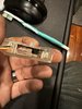
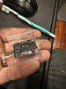
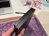
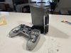
You should be able to add plenty more. The PS2 Slim power supply can deliver up to about 40 watts of power, waaaaay more than the console needs.Well added some LED's lol
Might ad 2 more but I want to run the system for a few and make sure its stable with the LED's install power draw wise
Let me know what you guys think
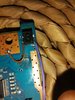
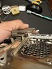
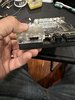
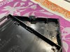
[EDIT] Just make sure you're pulling from the DC-in and not from random regs on the board.