Worklog Wii Miicro Deluxe+

Alvaro

.
Joined
Nov 29, 2016
Messages
98
Likes
50
Location
somewhere
Portables
2
Decided to finally come back and try and do some more projects. Going to be rebuilding my G-Wii soon (that I disassembled fully many years ago bc I was having issues lol).

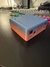
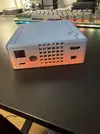
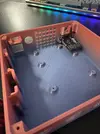
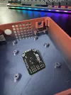
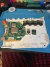
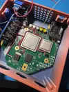
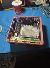
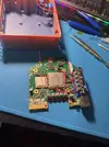
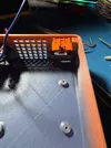
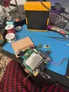
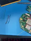
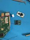
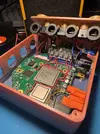
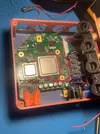
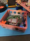
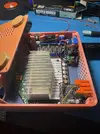
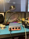
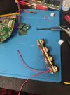
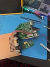
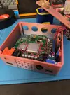
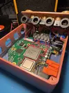
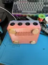
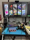
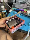
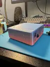
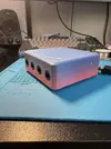
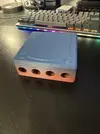
Starting slow with a Wii Micro build because I always wanted one! I’ve decided I wanted something like Benge’s that has USB PD and a push button switch but also equipped with hdmi. I edited the STL’s and created a version that uses analog2hdmi board from ElectronShepherd. Here are the pics :) prints came from a FlashForge Finder I got for free which is what sparked me to start this project in the first place! All it cost was filament and the PSU for the printer. I’d say the hdmi board fitment came out pretty sweet for first time adding to an STL or doing cad in general.

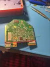
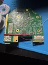
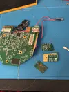
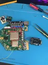
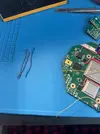
I also got my 6 layer motherboard working with U10 relocation already. Just gotta wait for RVL-PSU’s to come from @CrazyGadget that I purchased from Etsy.

P.S. if anyone needs any more RVL-PSU’s in about a month let me know. I’m going to be assembling about 10 and can sell some of them.
 

Attachments

  • IMG_5789.webp
    IMG_5789.webp
    500.5 KB · Views: 7
  • IMG_5790.webp
    IMG_5790.webp
    465.4 KB · Views: 6
  • IMG_5791.webp
    IMG_5791.webp
    455.3 KB · Views: 7
  • IMG_5792.webp
    IMG_5792.webp
    347.6 KB · Views: 4
  • IMG_5793.webp
    IMG_5793.webp
    404.4 KB · Views: 8
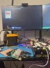
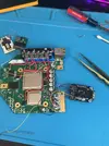
Little update. So I went ahead and trimmed the wii and it booted! Working on wiring stuff up right now but its looking pretty good. Some questions I do have however:

Am I good to use 30 AWG wire to power the Analog2HDMI 5v?

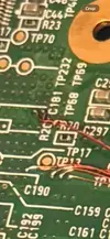
Is my sensor bar 12v wire correct? The diagrams have confused me a little bit… I hooked it up to pin 17, sensor 12v, and it seems that connects directly to the sensor PWM out and 12v spot (from Nolds diagram) but shouldnt there be a resistor in between to PWM out?

IMG_5951.webp


further more, I understand you need to power the pre amp with 12v but 13 on the leg of the pre amp and pin 13 on the port do not have continuity (another reason I didn’t solder the 12v to the port). So I just soldered directly to the leg from pin 17 where i feed the 12v to (is 30 AWG ok for pre amp 12v)?Pin 13 on the port also does not have continuity with the 12v spot from Nolds diagram (more confusion on 12v rails now).
IMG_5952.webp


This has all confused me, especially with less info on 6 layer boards out there. Help would be greatly appreciated!
 

Attachments

  • IMG_5941.webp
    IMG_5941.webp
    671.3 KB · Views: 4
  • IMG_5946.webp
    IMG_5946.webp
    801.4 KB · Views: 2
  • IMG_5948.webp
    IMG_5948.webp
    547.7 KB · Views: 2
  • IMG_5950.webp
    IMG_5950.webp
    714.7 KB · Views: 2
  • IMG_5949.webp
    IMG_5949.webp
    672.9 KB · Views: 3
Hi Alvaro, nice to see another Wii Micro buildlog! I'm certainly no expert, but I can give my 2 cents.

For the sensor bar, I've found that the easiest solution is getting a cheap USB sensor bar that works off of 5V. I simply plug that into the USB port of my TV, but any usb port will do as long as it receives 5V. Removes some complexity on the Wii side :D.
If you still want to stick with the original sensor bar, be sure to put the R164 resistor in series between 12V and PWM out as Nold mentions in his Wii Micro guide. It looks like you've already removed that resistor from the motherboard, if you've kept it safe you can reuse that.

Another thing you could consider is removing the preamp and connecting the pins from audio L and audio R directly. The downside is that your audio will be a bit more silenced, but if you remove this and go for an external sensor bar, you've basically removed the need for 12V completely. This allows you to run the Wii Micro of off 5V if you like.
 
Hi Alvaro, nice to see another Wii Micro buildlog! I'm certainly no expert, but I can give my 2 cents.

For the sensor bar, I've found that the easiest solution is getting a cheap USB sensor bar that works off of 5V. I simply plug that into the USB port of my TV, but any usb port will do as long as it receives 5V. Removes some complexity on the Wii side :D.
If you still want to stick with the original sensor bar, be sure to put the R164 resistor in series between 12V and PWM out as Nold mentions in his Wii Micro guide. It looks like you've already removed that resistor from the motherboard, if you've kept it safe you can reuse that.

Another thing you could consider is removing the preamp and connecting the pins from audio L and audio R directly. The downside is that your audio will be a bit more silenced, but if you remove this and go for an external sensor bar, you've basically removed the need for 12V completely. This allows you to run the Wii Micro of off 5V if you like.
Thank you for the suggestions! I’d like to keep all the original functionality so I’m going for the keeping. I figured out the PWM stuff, I overlooked a note a nolds guide stating if you power the pre amp you get 12v at that spot. Couldn’t believe my eyes when I read that… I basically had Sensor 12v pin hooked up to all the pre amp 12v which would have been bad. No wonder they were all had continuity. Still doesn’t make sense to me though that the pre amp 12v leg is not connected to pin 13 of A/V (pre amp marked 13 too).

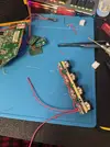
Anyways what I did was run 12v through the SMD filter because I wasn’t sure if it is required for the sensor bar. Then through the resistor and I put solder mask under it and glued it in place. The wire will then go to the port:)
IMG_5954.webp

still wondering about those wire sizes tho…
 

Attachments

  • IMG_5955.webp
    IMG_5955.webp
    514.9 KB · Views: 3
  • IMG_5956.webp
    IMG_5956.webp
    769 KB · Views: 2
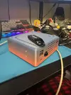
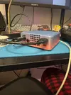
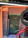
Basically finished up the system and its looking pretty good. Although bluetooth does not seem to be working and I can’t boot into home menu. Are my data wires too long do you think. All the slack is what is shown in the pic, pulled tight under mobo. Not sure what is standard length and how long will make it stop working.

Another side note, my reset button is not working either… Does anyone know if it should work in RVloader and GC games?

EDIT: It looks like I had my buttons ground connected to 1.8v BY ACCIDENT When I was looking for grounds I heard my meter beep and didn’t even look. It was just the low resistance of ground to 1.8v that made it beep… Anyways reset works now but not how I thought it would. It simply resets the current game you are playing and not the console. Also I was pressing the sync button quite a few times so that means I sent 1.8v into my bluetooth module sync and even holding it there. Could this possibly break the bluetooth module or is it more probable to be my wire lengths as seen.

IMG_5975.webp
IMG_5974.webp

IMG_5981.webp
IMG_5980.webp
 

Attachments

  • IMG_5967.webp
    IMG_5967.webp
    567.6 KB · Views: 3
  • IMG_5966.webp
    IMG_5966.webp
    808.3 KB · Views: 3
  • IMG_5962.webp
    IMG_5962.webp
    694.4 KB · Views: 3
  • IMG_5961.webp
    IMG_5961.webp
    734.7 KB · Views: 2
  • IMG_5960.webp
    IMG_5960.webp
    616.5 KB · Views: 4
  • IMG_5958.webp
    IMG_5958.webp
    515.4 KB · Views: 3
  • IMG_5957.webp
    IMG_5957.webp
    341.9 KB · Views: 3
  • IMG_5968.webp
    IMG_5968.webp
    735.9 KB · Views: 3
  • IMG_5970.webp
    IMG_5970.webp
    359.5 KB · Views: 2
  • IMG_5972.webp
    IMG_5972.webp
    518.2 KB · Views: 2
  • IMG_5976.webp
    IMG_5976.webp
    522.7 KB · Views: 3
  • IMG_5979.webp
    IMG_5979.webp
    293.4 KB · Views: 3
  • IMG_5978.webp
    IMG_5978.webp
    272.9 KB · Views: 3
  • IMG_5977.webp
    IMG_5977.webp
    459.7 KB · Views: 1
Last edited:
I'm no expert, but if your bluetooth module didn't have any ground connected to it at all, then I don't think it's possible to break it. It may be wire length, or it may also be the solder joints (on 4 layer Wiis you need to solder to .1mm traces, although I'm not sure how it works in this scenario, but I will say the soldering is incredibly challenging, so if you did need to solder to the traces here, it definitely could be the solder joint). I'm not real familiar with the rules bluetooth has for routing and whatever else, so I can't really answer whether the wires should be shielded, twisted with each other, roughly the same length as each other, super short, or what exactly. I will say you probably want to avoid routing it around any sources of interference.

If I'm not mistaken, it looks like your bluetooth wires are twisted with each other. You might try having them not be twisted.
 
I'm no expert, but if your bluetooth module didn't have any ground connected to it at all, then I don't think it's possible to break it. It may be wire length, or it may also be the solder joints (on 4 layer Wiis you need to solder to .1mm traces, although I'm not sure how it works in this scenario, but I will say the soldering is incredibly challenging, so if you did need to solder to the traces here, it definitely could be the solder joint). I'm not real familiar with the rules bluetooth has for routing and whatever else, so I can't really answer whether the wires should be shielded, twisted with each other, roughly the same length as each other, super short, or what exactly. I will say you probably want to avoid routing it around any sources of interference.

If I'm not mistaken, it looks like your bluetooth wires are twisted with each other. You might try having them not be twisted.
I have experience soldering to small traces so it shouldn’t be too hard for me IF i knew where the locations were for 6 layer. From my research the wires should be as short and twisted as possible, which I have now done….
IMG_5985.webp


unfortunately it’s still not working. Also I did have proper ground connected to the BT module so it sent that 1.8v to sync 100% and I even held it there trying to sync.

I can’t really take this apart easily to get to the vias now but I know they are for sure connected still after twisting it more bc of measurements I took. Honestly if there is a trace location I would attempt to solder there but it is not obviously sticking out like the one for 4 layers. I will show the via soldering from pics i took before assembling.

Maybe I should just try a new bt module and wire it. Would 1.8v to the sync pin really cause it to break? reset seemed to function fine after that whole ground mistake. i really just want my wiimote to work :/
 

Attachments

  • IMG_5980.webp
    IMG_5980.webp
    88 KB · Views: 1
  • IMG_5984.webp
    IMG_5984.webp
    237.7 KB · Views: 2
Well well well…. I feel really stupid. My sync switch was wired up to 1.8v then I wired it to ground. That’s twice I got it wrong! Thankfully @cy on discord pointed that out and it worked after I fixed that and wired it to 3.3v. Not sure how I missed that even after looking at the BT diagram so many times!

Lesson learned to test bluetooth with composite before assembling something that would suck to take apart (the modules were very press fit in and it was a bit finicky to assemble esp with my Analog2Hdmi). That was the problem, I couldn’t see the home menu because of VGA patches (which I wasn’t aware of for a bit) and I had no wiimote paired to this console previously. So I never knew if it was actually working first try and especially didn’t know it was the sync button which I could’ve known if i had a pre paired wii mote. In the end it’s all good tho thank you to everyone in the discord who contributed.

Also speaking of Analog2Hdmi I’m glad everything fit together first try editing the stl to add it:) it was a bit challenging to assemble tho. Some screws were hard to get and stuff had to be mounted in a certain order or else I wouldn’t have access to screws. Had a few close calls that could have made me need to revise it a bit.

Anyways I’m sure tightening and shortening wires didn’t harm anything and also probably didn’t need to run the sensor 12v through the filter component but I did anyways.

IMG_5989.webp
IMG_5988.webp
IMG_5987.webp
 

Attachments

  • IMG_5960.webp
    IMG_5960.webp
    616.5 KB · Views: 3
  • IMG_5962.webp
    IMG_5962.webp
    694.4 KB · Views: 3
  • IMG_5964.webp
    IMG_5964.webp
    795.9 KB · Views: 2
  • IMG_5972.webp
    IMG_5972.webp
    518.2 KB · Views: 2
  • IMG_5968.webp
    IMG_5968.webp
    735.9 KB · Views: 3
  • IMG_5997.webp
    IMG_5997.webp
    287.2 KB · Views: 3
  • IMG_5994.webp
    IMG_5994.webp
    703 KB · Views: 3
  • IMG_5996.webp
    IMG_5996.webp
    674.2 KB · Views: 3
  • IMG_5991.webp
    IMG_5991.webp
    571.8 KB · Views: 3
  • IMG_5990.webp
    IMG_5990.webp
    566 KB · Views: 2
  • IMG_5958.webp
    IMG_5958.webp
    515.4 KB · Views: 3
That's a super clean print dude! Happy I was able to help! I probably should've also remembered that tidbit about the sync button being pulled high when I was trying to help earlier, but it escaped me then. Cheers!
 
Back
Top