Worklog PS2V

Legend

.
Joined
May 10, 2019
Messages
201
Likes
362
Location
Canada Boi
Portables
2
So I've been sharing tad bits of this project on the discord and I feel like I have enough done to show you guys so I figured I would make a worklog finally. Ladies and gentlemen, I present to you: The PS2V

ProperPS2V.png


I've been sitting on a 79k PS2 for years in hopes of making a portable and finally decided to put my brain to work and make something. I have a small list of projects I have not finished and I'm hoping this wont also be one of them but I've been making good headway on it so I hope to have a finished product at some point. This will be my most ambitious project yet and I hope to have a lot of cool features implemented that I havent seen before, as well as implement all of the little cool things I've seen here and there throughout all of the PS2 worklogs I've been tirelessly researching. With that being said, I'm going to try my best to break this up into segments as I can ramble about this stuff forever but this bad boy will have some good features.

Features:
  • Custom Designed Shell Based on the PS Vita​
  • Custom Trimmed 79k PS2 with DAC Relocation​
  • Custom Controller Boards with DS2 Microcontroller​
  • 5 Inch 800x480 IPS Screen and Custom Driver Board with Shinobi Scaler 2 Integration​
  • Custom U-Amp​
  • Custom Power Regulator Board​
  • Custom FMCB Memory Card and MX4SIO for Game Loading​
Disclaimer:

I left some things out of the features list such as batteries as I dont know what I'm going to do for some things nor do I know how I'm going to fit some things in. As I said, this is my most ambitious project so some of my ideas may not even work, so everything is subject to change, but with all of that being said, lets get into it!

Custom Controller Boards:

So as some have may seen, I was able to figure out pressure sensitive buttons in a custom form factor using the original PS2 controller IC. Here is the worklog:


So to save the trouble of explaining my thought process on what controller to use and why, its all layed out in my previous worklog linked above. I tested both clicky dome switches as well as membrane buttons when I made my test board and both work great with pressure sensitivity! So I plan to re-use the PS Vita 1000 "X, Circle, Triangle, and Square" button membrane with clicky domes, the "Start and Select" buttons with clicky domes, the "DPAD" membrane with clicky Buttons, the original PS logo button as a power button and finally the original triggers + their membranes in conjunction with custom flex PCB's for L1 and R1. Ill get into what I'm going to do for L2 and R2 soon.

As for joysticks, I thought about a few options that were in a small form factor such as the original Vita sticks however they dont have the click switch I need for L3 and R3 so I landed on looking into switch joysticks. The issue with this was that they use digital signals as opposed to analog which I needed, and I really didnt want to figure something out to use digital sticks as there is a lot to figure out with digital to analog converters and then scaling and deadzones etc. so after some searching, I was lucky enough to find that K-Silver made switch joycon joysticks that were converted to analog sticks with 10k potentiometers so I finally landed on my perfect solution that works natively with the DS2 IC. The only caveat was that with the specific physical orientation they need to be in, I needed to invert the right stick. Luckily it was as easy as swapping VCC and GND and it properly inverted and worked great in my testing.

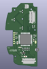
I'll get into case specifics after but I started to design my case and got the right side done, so I figured I would design the controller board while I'm at it:

Screen Shot 2024-11-11 at 9.03.02 AM.png
Screen Shot 2024-11-11 at 9.02.28 AM.png
Screen Shot 2024-11-11 at 9.02.47 AM.png


The routing isnt great due to space constraints and component placement but I have to work with what I have. Some things to note are that I need to cut off the screw post on the edge of the joystick that lays over the buttons but the other one will be kept. I have the little connector on the top for the R1 flex PCB but I also still have yet to add the connector for R2 as I still need to figure out the placement for it in my case design. The connector on the bottom is the data lines that will go to the PS2 however it is subject to change in a final revision. The connector on the side is for the remaining buttons that will be on the left side PCB once its designed.

Here is the Flex PCB design for R1 that I plan to use with the original Vita trigger membrane. I plan to extend it slightly and add a tiny resistor for pressure sensitivity requirements as I would rather have it after the button as opposed to before the button (if that makes sense) but we'll see. I also have yet to add the stiffener that needs to go where the edge connector fingers are but that will be added soon when I go to export the gerbers.

Screen Shot 2024-11-11 at 7.35.49 PM.png
Screen Shot 2024-11-11 at 7.37.20 PM.png
Screen Shot 2024-11-11 at 7.37.42 PM.png


The flex PCB will essentially be mirrored for the left side. But enough about buttons, lets move on!


Custom Shell:
As per the features list, I plan to use a custom designed shell that is essentially the Vita 1000, however I plan to also integrate it into the Vita Hori grip that @Wesk so graciously scanned, but ill get into that portion in a bit. Here is what I have so far, and ill try my best to explain everything:

Screen Shot 2024-11-11 at 8.14.45 PM.png
Screen Shot 2024-11-11 at 8.15.23 PM.png
Screen Shot 2024-11-11 at 8.15.48 PM.png


I plan to make this a 3 piece case, however I only have the top portion like 40% done. Currently the right side (right side when facing forward) is almost done. This includes my R1 trigger, and "trigger lock" mounts, my main button mount for the membrane, the analog stick mount, the start and select membrane mount, and what is going to be a chamber for my speaker. First we'll start by looking at the triggers.

Screen Shot 2024-11-11 at 8.23.08 PM.png
Screen Shot 2024-11-11 at 8.23.31 PM.png
Screen Shot 2024-11-11 at 8.23.52 PM.png


You'll see that I modelled the trigger, the trigger lock, as well as the trigger membrane that I plan to use with my trigger flex. These are not modelled exactly perfectly hence why they may look slightly off, however I made sure to quadruple check my case design as opposed to the components to make sure that the IRL components fit as best as they can.

Next is the "X, Square, Triangle, and Circle" buttons and membrane:
Screen Shot 2024-11-11 at 8.30.45 PM.png
Screen Shot 2024-11-11 at 8.31.08 PM.png


Again, it may look slightly off but the case is what matters here. You'll also notice that the shadows on my concave loft make it look like theres a dent, but I assure you there is not. Benge made a good model of the buttons and membrane but I made my own as I wanted a little more detail added for the aesthetic's. Next up is the start and select buttons as I'm saving the joystick for last.

Screen Shot 2024-11-11 at 8.35.39 PM.png


This is Benge's model of the start and select as I still have yet to make one myself with the logos on the other side, and this one looks wildly off so thats something ill need to double check. Next up is the joysticks:

Screen Shot 2024-11-11 at 8.37.53 PM.png
Screen Shot 2024-11-11 at 8.38.15 PM.png
Screen Shot 2024-11-11 at 8.38.29 PM.png


I had to model this one myself and you can also find it over at the model repository in the forums. Im going to have to trim the screw post off as it interferes with the buttons but other than that, the PCB that it mounts to will keep it in place as well as the little "walls" that ive modelled around it. Onto the screen:

Screen Shot 2024-11-11 at 8.42.29 PM.png


The screen placement ended up being a quite crucial detail as it stopped me from being able to keep the original dimensions of the PS Vita as the OLED screen in the original was 2mm thinner horizontally than the 5 inch screen you see here, so that caused me to have to extend the whole front case about 4.5mm to accommodate this. It sits in its own little "bay" of sorts and the case still needs a cutout for its connector etc. I really wanted to use the original screen acrylic that was on the vita but with it having to be stretched, I'm not able to. I do have an idea to get a custom piece of acrylic cnc'ed and black everything out except for the viewing area of the screen but we'll see how that turns out when the time comes. Here is a little nude shot of the controller PCB in the case (dont mind the weird .step that kicad exported):

Screen Shot 2024-11-11 at 8.49.40 PM.png


Other than this, theres just the hole on the side for the speaker chamber which still needs to be sorted, but I'm still working on the top half and will figure more things out as I go. After the top half is figured out, I still need to "reverse engineer" the Hori grip that Wesk scanned from a mesh to a solid body so I can work with it and go from there.

Screen Shot 2024-11-11 at 8.53.10 PM.png


R2 and L2 will reside in the back portion of the case and I plan to remove the bottom triggers all together as they're not needed. Given I can pull this off, it'll be sick! Enough about cases though, lets move on!


Speaking of moving on, its getting late as I write this worklog and I dont trust my laptop to save this as a draft so ill post this for now! Ill finish writing my ideas tomorrow and edit this post or just double post like a degenerate lol Until then!
 

Attachments

  • New Project (3).png
    New Project (3).png
    10.9 KB · Views: 165
  • Screen Shot 2024-11-11 at 9.02.28 AM.png
    Screen Shot 2024-11-11 at 9.02.28 AM.png
    123.4 KB · Views: 157
Last edited:
Time for me to double post like a degenerate lol. I dont really have much pictures for the rest of my ideas but ill I'd like to get them out there so we'll continue on!

Custom Trim:
So theres not much to say about this. My trim will pretty much be the advanced trim but trimmed further to the ethernet IC. I plan on replacing the DAC with something like the THS8135 as it draws less power and generates less heat. This relocation will be required as I dont have enough space to fit the regular advance trim even if I wanted to. It'll also be a great test of my skills as ill need to create another custom board that flows nicely with the PS2 PCB as well as wire 21 tiny wires for the RGB888 lines. I've also thought about trimming some more off the top where the memory card and controller traces will be however I'll see what dimensions the board is once I trim the max amount off the bottom. I've raw dogged micro soldering since I started years ago but with this project, I think its about time I get a microscope for something like this as i want to be able to concretely verify all of my joints etc. I havent touched the PS2 trimming wise as I still have some things to test and even when trimming, I plan to do a plethora of tests as I go because this will be my first PS2 trim and I dont want to mess anything up. I'm pretty confident in my trimming skills so we'll see how it all goes when the time comes.

Screen & Driver Board:
As per the feature list, I plan to use the 5 inch 800x480 screen sold on the 4layer website in conjunction with Yveltals Shinobi Scaler 2. My plan is to order a screen and 2 driver boards and reverse engineer one of them. I dont plan to do much custom work to it, I would just pretty much like to have a custom board to transplant all of the components onto so I dont have 2 boards for my screen. As for the Shinobi Scaler, Ill see what Im able to do with it to integrate it into the same board to have a nice driver board / scaler in one board. This is all subject to change but we'll see how it goes.

Audio:
Theres not much to say about the audio other than Ill be using Gmans open source U-AMP made into a custom board to fit where I need it to be. I've been taking a little look into speakers and I'm still unsure which ones I would like to use however I still do have an old U-AMP from when the Bitbuilt store was still a thing, so maybe ill test some different speakers out to see what will work best for my use-case.

Custom Power Regulator Board:
This is where my ambition comes in as this will be a true test of my skills and also where I see the most troubleshooting happen. Ill sort of preface this by saying i have no clue how to code however I'm a quick study and have a burning determination so im only half confident that Ill get this all to work. The custom regulator board will be heavily based on the original open source RVL-PMS however there are a few changes as well as things that are added. I had planned to use the original 16 pin PIC that is used and possibly modify the code to do what I wanted it to do however I realized that with all the things I want to have, the 16 pins werent enough, so I landed on using the PIC16F15344-E/GZ as it has 20 pins and it seems like it will do what I need it to.

The board will use the BQ25895MRTWR in conjunction with the HUSB238 for charge and play, I have 4 regulators currently: 1V, 1.8V, 3.3V and 5V, I plan to use an ADC pin with a thermistor for thermal protection as well as to drive a PWM controlled fan but I may need a level shifter for that. I plan to use another PWM pin to drive an addressable LED for power and charging indication, I want to use the MAX17055 for a battery gauge but we'll see about that. Other than that, I cant think of much other features I have at the moment as this was the first thing I started working on and I took a long break from it to work on the case design as it was hurting my brain lol. As for form factor, I really wanted to have it mont to the PS2 itself in a QSB style similar to Loopj's power strip, or the Thundervolt, but with certain components on the PS2 mobo sticking up, I'm not sure how much space I have to do this, and even in the area I'd like to put it in, it will have to sit above some small capacitors so it wont be flush to the board anyway, so that idea is just an idea for now. Another concern I had was there might be too much noise for everything as it would sit under the main chips on the PS2 so as much as I would like to do something like this, im prepared for it not to work.

Here is what I have in terms of a schematic. Things may not be right but I plan to go thoroughly through it at some point:

Screen Shot 2024-11-12 at 8.08.54 AM.png
Screen Shot 2024-11-12 at 8.09.08 AM.png
Screen Shot 2024-11-12 at 8.09.20 AM.png

There's the regulators, the charging circuit, fan control circuit (which I think I may need to add a level shifter for) and the 5v path switch, and I still have yet to add the PIC and BQ chip as well as the MAX17055 if I plan to use it. everything here is pretty self explanatory but ill explain the 5v switch. I plan to have 4 enable pins on the PIC for different things. EN1 will be for the 1V, 1v8, and 3v3 regulators, EN2 will be for the 5v regulator, EN3 and EN4 will be for the 5v path switch IC. When the button is pressed to power on the board, EN1, EN2, and EN3 will be pulled high to enable all the regulators as well as the "main path" for 5v. When the system is off and the BQ detects a charge, EN4 will be pulled high to enable the 5v regulators "alternate path" to power the GL823K to allow me to do file transferring (which ill get into now)

I have a circuit to use an SD card with the PS2 for MX4ISO loading but when the system is off, the SD lines will go through the FSSD06 mux to the GL823K for file transferring. Unfortunately the FSSD06 was the best option I found for a SDIO mux that my brain could understand and its at its end of life cycle so I need to order some before theres none left. This gives me a chance to segue into my next and last topic.

Custom FMCB
For this I plan to install all of the required files I need for my FMCB memory card and reverse engineer it to put it onto a flex pcb or something of that sort so I dont just have a mem card PCB hanging around in my portable. Theres not much else to say about this however I have peeled apart like 5 of my mem cards and found the best one to work with. Thankfully Tschicki has a schematic on his worklog I can reference for this so I'll be getting to it soon enough.

Conclusion
Again, I'll say that this is my most ambitious project yet and it'll take me a long time to complete due to time constraints and the absolute ton of work I need to do on this. I'll also say that some of these ideas may not work however im determined to try. I'm primarily working on this project at the moment and my next steps are to keep working on the top half of the case and maybe order my screen and driver boards to start the RE process on that so I can have the top portion fully finished before moving onto other things, but my ADHD brain is all over the place so we'll see what gets done first. I'll update soon enough! Thanks for reading!
 
I can't wait to see where this goes!! This project is definitely gonna turn out great.

Are you planning on sharing your designs for the screen driver with the shinobi scaler integrated? Because that sounds like it would be really awesome to have in a portable

Also, I may be wrong here but from what I can remember, there is a 3rd party memory card that still functions with FMCB that also has a remarkably simple design that would be easy to replicate. Max Memory cards (the black/gray ones with the orbital graphic on the logo) would be easy to integrate.
 
Thank you!

As long as I can implement everything cleanly and it works as intended, I wouldn't mind sharing the designs!

Also, I may be wrong here but from what I can remember, there is a 3rd party memory card that still functions with FMCB that also has a remarkably simple design that would be easy to replicate. Max Memory cards (the black/gray ones with the orbital graphic on the logo) would be easy to integrate.

I'm just doing the 8mb magic gate memcard for now however I'll look into other options when I have the funds to do so! Most of the third party cards I've seen have an epoxy chip but if there's a reliable one out there that works with FMCB and has chips i can transplant, then I'd have no problem using one!

*Edit*
I just ordered one of the 64mb max cards that you mentioned and will get it in like 2 weeks, so I'll peel it apart to see if it's usable in my case. Thanks for the recommendation!

One thing I've seen is that some games expect an 8mb memcard and won't save unless there is one. I'm not too sure of the truth in this but once I get the memcard in, I'll find a game that claims to need a 8mb card and try the third party one out.
 
Last edited:
Update time!

This is mainly a FMCB update but I have a few other things to add at the end.

FMCB

So I've been taking a break with my case design and decided to start looking into the memory card aspect of this build. I wanted to implement some sort of custom board so everything flows nicely and I think I may have something. I have like 5 official memory cards so I peeled the shell off of each of them to see which one looked the simplest to reverse engineer, and by this I mean which one had the least amount of components. Im surprised that most of these memory cards have what I think are a stupid amount of extra components as the one I had in my collection that I decided to use seems so simple compared to the rest.

Either way, I depopulated the one I ended up choosing, set the components aside for later, and ended up scanning the card even though its a simple design. I figured it would just make things more easy for me so heres what I got:

1000004545.jpg
1000004547.jpg
1000004548.jpg


So this card is fairly simple compared to the other ones I have. It consists of 6 resistors (one of which is a 0 ohm), 4 capacitors, a ferrite bead, a crystal, a reset IC, and of course the main components. It didnt take long to figure out what everything connected to, to be able to get a schematic and PCB started.

Screen Shot 2024-11-20 at 7.12.10 AM.png


Once I had the schematic finished, I had to figure out where I wanted my PCB to be placed and upon checking over the trimming guide, I was a little disappointed as I wanted this to be on the back of the motherboard without having to run any wires around the board but the back has every connection point for the memcard traces aside from CMD. After figuring this out I started trying to sort out where I could place the PCB on the top side of the board so I asked in the discord how sensitive all of these components were and showcased a hypothetical placement and was told that I should be fine, so this is what I came up with:

Screen Shot 2024-11-18 at 2.42.56 PM.png


This still fits within the boundaries of the advanced trim and I planned to have it connect directly to the necessary traces on the mobo via castellated pads. having my flex PCB in this location also allowed me to connect to the memcard 2 traces for my custom MX4SIO as well the controller 1 data lines to be able to break them out for easier connections. After some crucial component placement choices and careful routing that I had to clean up a few times, I ended up with a pretty good looking product:

Screen Shot 2024-11-20 at 6.42.47 AM.png
Screen Shot 2024-11-20 at 6.43.08 AM.png

Screen Shot 2024-11-20 at 6.43.25 AM.png


So this has castellated pads for all connections as well as 2 ground connections to the mobo. This theoretically should also work and fit nicely where I want it to. I probably didnt need to length tune the memcard 2 traces but I wanted to be sure as they are going to be connected to my SD card. This is just a test board for now but ill probably add connectors for the memcard 2 and controller data lines in the final revision if theyll fit just to keep the wires to a minimum. With that being said, I uploaded the files to JLC to get a quote and they didnt have any issues when reviewing the files, so I ordered the boards as they also werent charging me an arm and a leg.

Screen Shot 2024-11-20 at 6.51.06 AM.png


My only issue was that the cutouts werent showing up in their gerber viewer, however it wasnt an issue with the gerbers as I checked with a few other gerber viewers and the cutouts showed up fine. I also searched around and read that people have had this issue before with the JLC viewer but their boards still came out fine so im not too worried. I also added a remark stating that there were cutouts so fingers crossed.While I wait for the boards, I still have to make a mouser order to get the rest of my components so ill be doing that later today.

As per my previous conversation with Jonny above, he recommended me a good 64mb card that is known to work with FMCB and has a simple layout so I ordered one but cant be sure when itll be in as Canada Post has recently gone on strike, so we'll see when that is but once I do get it, ill do some thorough testing to see if its a viable option.

as for other aspects of this build, I cut the portion of my case that was mostly finished and ordered it just to test fitment so that should be here within the next few days!
Screen Shot 2024-11-20 at 6.51.23 AM.png


It was stupid cheap so I couldnt resist lol. I have also ordered a screen and driver board so once it gets in, ill reverse engineer it to start getting my custom screen board done. Thats it for now! Ill update again once I get everything in to test fitment and to see if my FMCB flex works.
 
Update time!

So this isnt a huge update however I figured I would share what ive been doing lately.

Right now I'm sort of at a stand still with some things as I've been trying to have a specific work flow to make sure I'm not getting too ahead of myself and with the Canada Post strike happening, no parcels are coming in or going out so im limited to what I can do until something is figured out and I can get the items I ordered, but heres where im at:

I currently have 3 packages stuck in the strike, and those are the one half of my case, my memory flex PCB's, and my screen and driver board. I want to wait for my case to test fitment before continuing with that as Id rather make the changes that I need now so it'll lessen the workload downstream if changes are needed, so theres not much I can do until I get that. I want to wait to test my memory flex PCB's before I trim the PS2 as Id rather test what I can with a fully in-tact PS2 to minimize troubleshooting if theres any issues, and lastly I need to wait for my screen and driver board before I can start the RE process on it of course.

I do have a custom video DAC started however I want to wait until I trim the PS2 and test my voltage locations to get an idea of what my board layout and edges are going to be so I can figure out what the board layout and edges are going to be for the video DAC as I'm not working with much space. To test voltage locations and how I'm going to manage that, I need to have a PSU of some sort as I dont want to get into the PMS aspect of this build until I'm ready for a final-ish layout so that brings me to my next topic:

PS2-PSU
So in order to test my trim without having the full PMS designed, I needed a quick PSU-esk solution specifically for testing. Customledmods has the beautiful "Power PS2" board, but after looking into the components, I did have a few concerns/ things I wanted to personally change. One of my concerns was with the 1.25v regulator outputting a max 3A when the PS2 is capable of drawing 3.1A on the 1.25v line. Given he hasnt had any issues as far as I know in the portables I've seen him build using his board, I still wanted to make sure everything was up to spec to avoid issues in the long run. Another thing that I personally wanted was to test the more standard voltages such as 1v instead of 1.25v, running both the 1.75v and 2.5v lines at 1.8v, and using 3.3v instead of 3.5v. One more thing I had a concern about was using 0603 capacitors. Yveltal informed me that after derating, the 0603 caps wouldnt be up to par so package size does matter. Again, customledmods and MisterM made a beautiful board that does work, but I just had a different vision.

So after some deliberation and recommendations via the discord, I ended coming up with a product of my own:

Screen Shot 2024-11-28 at 9.07.06 AM.png

Screen Shot 2024-11-28 at 9.07.34 AM.png
Screen Shot 2024-11-28 at 9.07.48 AM.png

Screen Shot 2024-11-28 at 9.08.04 AM.png


This is the PS2-PSU, and im not going to get into specifics about it right now but dont worry, I've ordered the boards and components (and paid a gross amount of shipping to get them early, let alone at all (thanks canada post lol)) and am going to test it out when they come in and given everything works the way I'd like it to, I have no issues releasing the board files for those who may want to build one as well as maybe sell a few assembled boards if theres enough of an interest for it.

Once I get the boards and test where all of my voltage points are going to be, I can then get an idea of my PMS board layout to be able to get started on that. After that, I will be on a complete stand still until I get the rest of my packages in. I should get these boards in next week and will be able to test them so as long as they work, ill update again and itll be the last update before I get things in, so be on the lookout for the files if your interested!

Until next time!
 
Decent update time!

Theres been a few revelations as of late for this project so let's get right into it!

As I waited for my PSU boards to come in, I figured I would start trying to iron out the software side of things of this build so I didn't have to deal with it later on but I ran into some issues. I had soldered an SD card adapter to the memory card 2 slot similar to that of the ultra ps2 slim however nothing was showing up anywhere and in hindsight, I think it was the version of OPL and uLaunchELF that I was running just wasn't detecting anything. I made the mistake of trying to test with the bare board out and it proved to be quite detrimental. Things weren't working so I resoldered the adapter and went to go plug everything in and what happened next took a piece of my soul lol. As I plugged everything in, I saw the red light come on my little power button board as it should, but then it turned off and never came back on.

I started searching and going through the list of potential PS2 killers such as blown fuses etc. but everything checked out aside from the fact that I wasn't getting the 3.5v standby. I kind of narrowed it down to either one of the main components had shorted and fried itself, or one of the regulators or switching IC's had decided to go on a permanent holiday. I hadn't intended to trim the PS2 yet because I wanted to keep everything in tact for as long as I could for testing with the hopes of minimal troubleshooting but I had no other choice to do it. I guess I could have removed some of the regulating components and tested that way but I figured if I was this far into it, I might as well perform my first PS2 trim.

Trim.jpg


Don't mind the dirty hands lol, I had just gotten off work and had minimal time to get this done. Im no stranger to Wii trimming so this wasn't too bad. I removed all components on the trim line and got to work, then filed, then sanded, and it turned out quite well. I still had a small sadness not knowing if it was still alive but I was happy to have a good looking trim.

Then came the PSU! I had gotten all my components in on Monday, and received the boards on Wednesday so I was really happy to have been able to get it assembled and tested. I had some small issues along the way like the regulators not having clear markings but I was directed to just swab them with some IPA and that seemed to have cleared things up for me. Another issue I had while testing was the 1v regulator wasn't outputting anything but all it needed was a reflow and it worked! Thanks to the fellas who were in the discord voice chat while I was doing this! the hype was well appreciated! Here are some photos of the process! (Also don't roast me for getting lead over Enig lol, the cost of shipping was 3 times the amount of the order and I had to cut costs somewhere but given I ever order the board again, it will be with Enig!)

BoardTop.jpg
BoardBottom.jpg

Stencil.jpg
Paste.jpg

AutobotsAssemble.jpg

This was my first time assembling a board with solder paste and all I have to say is wow! I think the hardest part of it all was placing the components (mainly the 0402 resistors) because I had shaky hands that night but other than that, the finish is great compared to hand soldering. I was and am super pumped that I have a working product and although its just for testing in my use case, it kind of restores my confidence a little in doing this!

I had a little more time that night so I decided to try to hook everything up to see if it would boot and it wouldn't. Ill put some pics of my wiring but as you'll see, I didn't connect all the voltage points as suggested in the trimming guide which was my issue, but I decided to put it away for the night as I already felt pretty good about having a working reg board.

WiredTop.jpg
WiredBottom.jpg


After all of this, I figured out where I was missing the necessary voltages and got to work last night to connect everything together. Keep in mind I still may have had a dead trim so while I had hopes, I was prepared to be disappointed. Upon hooking everything up and hitting reset, I wasn't getting anything for a minute so the sadness started creeping in until all of a sudden I saw that beautiful PS2 splash screen.

Boot.jpg


This was a true win for me seeing as how I thought the board was dead. I decided to take my win and stop tinkering for the night but I did try once more to boot it again and it wouldn't, so ill be tinkering with it tonight to see what I can get figured out. From here I plan to reconnect the USB and controller/ memory card slots to test some software things and that will be that until I can get my other parcels in.

On that note, I've been toying with the idea of using XEB as its more customizable and has a more appealing interface than the typical FMCB software. The only caveat from what I read is that is cant load from the SD card (or memory card slot) so if I use it, i'll design a small internal USB module with a SD card port, and a GL823K for XEB to reside on. That way if I need to update or anything like that, all I'll have to do is put the files on my MX4SIO SD card and transfer them to the internal SD card via uLaunchELF.

Thats all for now folks! I'm hoping Canada Post will come to a decision soon with its strike for the workers of course, but also so I can get the rest of my packages in to continue on. Thanks for reading!
 
Update time!

So for the past little bit while ive been waiting for my packages that have been stuck in the strike to come in, I have been diving into the world of C coding, PIC Microcontrollers, and I2C etc. Im happy to say that as a complete beginner to it all, I've been able to interpret code decently well however there is still a a lot I still dont understand fully so I've been keeping at it and even started coding for my PMS. At this point I feel it is the coding aspect as well as my case that will take the longest in this project. Some good news though is that I have some new ideas that I would like to implement however I'll get into those in a later update once I have something more concrete.

Another bit of good news is that canada post was put back to work last week so I've been able to receive 1 out of the 4 packages that I had stuck so far and that happened to be my memory card flex PCB's. They had oddly delivered them at like 2am so I caught the package while on my way out of the door for work but I had quickly threw one on the PS2 to see if it would all fit and unfortunately not all of the points lined up :(

I thought about this throughout the day and figured I would assemble one anyway and bodge it on there the best I could to at least test if the main memory card circuitry worked. Here is it assembled:
memflex_assembled.jpg


There was a few problems I ran into while assembling this as well as placing it. One being that the footprint I made for the original crystal was almost too big it seemed so it was a little difficult to get it on there, another being that the hole I had made for one of the resistors didnt line up, then of course some of the actual little castellated pads seemed too small and that there wasnt enough meat to solder to and they werent lining up correctly. Rest assured, after some contorting I ended up getting it on there.
Flex_Onboard.jpg


I didnt solder the breakout points and really only focused on the traces that were going to the memory card circuitry to make sure this all worked. I had to run an extra ground wire and of course the wire for 3v3 then turned the PS2 on and prayed with whoever I was in the BB voice chat with at the time.

Flex_Boot.jpg


By the grace of the Bitbuilt gods, it booted into FMCB and I was able to let out a nice sigh of relief. After being able to confirm this, I started looking into the issues I was having so I could make a better revised version that would actually fit and here were the things I faced:

- The scan I used wasnt scaled correctly so my points didnt line up
- While the castellated pads worked, there was not enough pad to solder to
- Because of scaling issues, the hole for one of the resistors didnt line up
- The flex covers the traces needed for USB lines if they are desired
- The flex covers the only convenient pads present for I2S audio (but I think im okay with that)
- I DIDNT DO PAPER PRINT TESTS lol

So I took all of these issues into consideration when making a new revision and I think I have something that is a lot better now:

Screen Shot 2024-12-22 at 5.35.00 PM.png
Screen Shot 2024-12-23 at 9.29.52 AM.png


Here is the real MemFlex™. I made sure to do a few paper print tests along the way to make sure everything lined up like it should have and I seemed to have got it down. Kicad was great with the scaling and all I had to do was cut out the small holes using my craft knife and test the fitment.

Paper.jpg


The new revision is scaled correctly and lines up great, the castellated pads have more meat to solder to, I added 3v3 and GND pads for the breakout connections in case I need them for testing, I added a small hole that reveals the USB traces with edge connecting fingers to act as a breakout if needed, I no longer have the need to run a 3v3 wire to the flex as one of the new through hole pads gets soldered directly to a 3v3 point on the edge of the PS2, and I swapped out the original crystal oscillator for an off-the-shelf option. Christmas has me broke so ill wait to order these and I may make some component changes as needed like the ferrite bead and the reset IC so the only things youll need from a memory card to make this work will be the 2 main IC's and everything else can be ordered.

aside from all of this, Im still waiting for the test print of my case (which should be in within the next week), my 3rd party memory card (which im not too concerned about), but the one thing im really excited to get is my screen so I can start reverse engineering it to work on that portion. In the meantime ill continue to test software as im still undecided on using straight OPL with FMCB or using PS2BBL with XEB, and ill also be learning a lot more about the coding aspect of my PMS to get something on paper.

Upon looking into the desired layout of my PMS, I realized its gonna be harder than I thought so I may make a new PSU revision that mounts directly to the board to test fitment etc. but we'll see how that all goes.

Until next time!
 
Heres a little update for you all!

This past Christmas break I haven't been doing too much in regards to the project because 2024 was a long year and I needed the break lol but I did do a little bit of stuff and had some idea changes that ill get into now.

ill start off with my case. I ordered a sliced piece of my top shell a while ago and it had got stuck in the strike for a fair bit of time but one day over the break I checked the tracking and noticed it was finally delivered so I was able to test some of the fitment of my physical parts.
1000005431.jpg
1000005432.jpg


I very prematurely ordered this because I was excited to test some things before continuing on the case as I wanted to avoid having to come back to do edits when I was way downstream and I wasn't disappointed. Everything seemed to fit quite nicely but the only issue I had was that the "pegs" that the trigger lock sits on were a little thin so it wasn't a press fit compared to how the actual Vita is, but a quick change is all I need for that to work better. the trigger pressed very nicely with the membrane in there just as the original vita would, so I believe I should be good on that front. aside from the trigger lock pegs, fitment for everything else was pretty good and even the vertical fitment for the screen was mint. without being able to test button presses with the controller PCB and whatnot, i'm pretty happy with the outcome! I realized that I'm going to hold off on the case design until I have most of my hardware designed and done so I can design the case around the hardware as opposed to doing things in tandem to avoid the headache of having to redesign if there are any hardware changes. I'm not totally forgetting about the case as I go because some things will need to be designed and tailored to the case itself so ill be keeping it in mind as I go.

as far as the PSU and soon to be power management system goes, I wanted to have it be mounted to the PS2 itself as previously mentioned, and I also wanted it to be as easy as possible given somebody down the road wanted to replicate this but unfortunately there are going to be a lot of tedious little relocations for it to work nicely. Ill get into that now:
Screen Shot 2025-01-06 at 8.10.04 AM.png


So everything on the bottom of the PS2 in the area I plan to have the PMS mount to are all pretty much 0402 components, so mounting it relatively flat enough to be able to solder castellated pads directly to the voltage rails is possible (aside from the bulk caps which are accounted for). To avoid having little cutouts for each of the bigger capacitors, I've decided that I need to relocate most of the caps in red to the top of the board as best as I can and some will need to be relocated in other areas on the bottom of the board. I tested the resistor array circled in yellow and it seems to be a 10k RA, so that will have to be replaced with either a smaller 10k RA, or with 4 0402 10k resistors for it to be flat. the "PS14" fuse will most likely be removed all together and the 2 points will be joined by one castellated pad on the PMS. The component circled in blue will have to be relocated to an area right under the bios chip with 6 wires coming from its pads but I hope to do that as cleanly as possible. Aside from all of that, the 0 ohm resistor on the bottom left of the board will be removed all together as the DAC will be removed in the final trim, and the other one above it will be removed with its 2 points soldered together.

I've relocated some of these components already but still have yet to relocate all of them and test the board afterwards. Once I do confirm everything works, ill probably make another PSU revision that mounts just like the PMS will for testing and go from there.

The Screen
I've had a lot of thoughts about screens and displaying information such as battery life etc. so I figured I would share it here.

After thinking long and hard about wanting to have some sort of on screen display for battery life, possibly temp, and charging state etc. aside from just a LED indicator, I quickly realized that im no Aurelio (being able to do it via software on the wii) or Tchicki (being able to do it via his custom syscon and FPGA) so I first had the thought of integrating a tiny OLED screen that would connect to the PMS via I2C to display information and have it be mounted on the top of the PS2V. After some thought about it, I realized it would be difficult given the spacial constraints of the case as well as having the extra power draw so I scrapped that idea.

After searching around some more, I started to dive into the idea of doing a custom firmware for the RTD2660/ 2662 chip on the screen that I plan to use. I've seen that BocuD has done it on his Swiitch 2.5 and I figured if I could bypass having the Shinobi Scaler 2 at all, then that would be more ideal as I could avoid the extra power draw and get some more battery life.

So my new thoughts are: A custom firmware for the RTD based LCD driver board that displays a custom PS2V splash screen, removes the "no input" blue screen, can accept 480i and properly de-interlace the 15khz VGA signals, and that can display battery and charging status via I2C, all of which the RTD is capable of. The big caveat for me is being able to actually modify the very few (not very good) firmware base's out there to do all of this. BocuD's firmware can display his splash screen and display his battery info, and there are binary's out there for accepting 15khz VGA but to be able to combine the 2 to make something that is mine for the PS2V is going to be difficult as I have little to no clue what I am doing lol. One thing I do have is a burning determination and willingness to learn so ill be diving down this rabbit hole head first.

My screen is still stuck in transit and I've been in contact with both the seller and canada post about it so hopefully I can get it soon. Aside from that, I plan to get a FT232H board (or adafruit 2264) and any other necessary items for programming to test firmwares and attempt to modify things to work with what I have. I've been looking into the idea of working with the firmware base I have, but also potentially trying to decompile the binary's out there that support 15khz VGA to try to understand how they work. I have a data sheet and have a good idea of the registers that need to be looked at as well as have an idea of how everything needs to be scaled but now its just a waiting game to get my items in for testing. I've also found out that some games like to switch between 480i and 240p on the fly so thats also something I'll have to look into. If for some reason I cant figure this out, I plan to default back to the LDC + Shinobi Scaler 2 combo, but hopefully I can get something working here as I'm sure a lot of people in the community can benefit from a custom firmware that supports 480i.

Enough about screens though, I have a new revision (and hopefully one of the final) of my Memflex that I plan to order soon but with shipping prices being the way they are from both PCB manufacturers and component suppliers, I've been trying to get as much done as possible to be able to order a bulk of things as once as opposed to paying up to $36 for shipping each time I want something.

This is it for now and maybe for a while as I get things sorted! The next update will hopefully be a banger for you guys so stay tuned!
 
wow, what an update this was, I really forgot to follow this topic, this Ps vita model really pleases me, and I'm not even going to mention the personalized memory card, it looks incredible to me! great work looking forward to more.
 
Update time!

So I've largely put this project on hold as I dove down a sub-project rabbit hole that is the RTD2660, and I've made some really good progress! You can find the separate worklog here:


I have 2 separate goals with the RTD2660 custom firmware, and I've outlined some of those goals in the worklog above but I have also been working with some of the fellas to aid in giving the community a universal driver board of sorts. That will most likely be an ongoing project for a while as we work to get things figured out. Now for the PS2V goodies!

Since I've been able to actually look at a code base to figure out what I can do, I feel I'm finally able to outline the features I want specifically for the PS2V. They are as follows:

- A nice crispy startup logo for the PS2V ofc
- Deinterlacing support for the VGA inputs as well as possibly add support for YPbPr if i so desire
- On-screen displays for charging state, battery life etc. Once I get my pms code sorted
- Since the open source audio amp is going to be on the same board as the custom driver board, my RTD2660 has support for on-screen audio (even though there isn't an amp on most of the RTD based driver baords) id like to see if i can get it working with the U-Amp to display my volume levels

With that, there may be other small features implemented once everything is said and done but we'll cross that bridge when we get there.

Aside from that, I've relocated almost all of what I need to for being able to test how my PMS will be mounted to the PS2. It's just a matter of relocating one more capacitor, designing a test board, and ordering it etc. For testing.

On top of that, I've received the 64mb max Memory card and it seems to be perfect for making a new revision of the memflex however, with the new developments in the PS2 scene such as using an SD2PSX type memory card with the new MMCE protocol, @mknrls and i have been toying with the idea of making an internal memflex that has all of the SD2PSX components as it would be an endgame solution for PS2 portables. We've also talked about making a revision for non-potable PS2's but there's still a lot in the air as we've both been pretty busy with things.

I'm largely trying to get most of the stuff ironed out for the custom RTD2660, but once I get it all figured out for the most part, the plan is to go full speed ahead with the internal SD2PSX, and finish up testing fitment for my PMS so I get get that coded and working in conjunction with the RTD2660.

That's all for now! I'll update as soon as I progress further! Thanks for reading!
 
Not a major update, but we're going in the right direction!

As per my RTD2660 worklog, I explained that I've been trying to do things sequentially and after about 3 weeks of messing around with the screens firmware, I was finally able to get the PS2V logo baked in. Now when the screen is turned on, the logo is shown and it will also show when there is no signal.

1000012238.jpg


After I got this working, Immediately hooked my trim up to the screen to see what kind of state it was in in terms of showing any kind of interlaced signal and that led me to find out that my trim was dead. It's weird however because it worked before I put it away to do screen stuff so I'll have to tinker with it and revert some of the little relocations I did to see if I can get it working again. Worse comes to worse I'll just have to get another 79k but I'm pretty deep into the screen stuff at the moment so I'm not too worried right now.

I do have a 75001 ps2 I peeled apart to find all the necessary connections for vga and hooked it up to my screen for testing. My next steps in terms of deinterlacing are finding the portion of code that handles VGA, coding in support for 480i, adding a function to check the input for an interlaced signal, and applying deinterlacing if the screen determines that the signal is interlaced. Once I get some sort of picture on the screen, I then have to mess with the deinterlacing registers to fine tune it so we can get the best output possible. Here is the current setup:

1000012260.jpg


In other news, I did start trying to get an internal SD2PSX figured out but it isn't as straight forward as I'm not working with a lot of space at all. This will include all of the SD2PSX components plus a SD mux to switch between the RP2040 and a GL835 for external file transfers so I don't have to peel it open everytime I want to add a game etc. I also plan to make a daughter board with the oled screen, buttons, and so on that connects to the internal flex via a ribbon cable so it can be initially programmed then removed. Here is the current state of that:

1000012261.png


There's a bunch of work that needs to be done and I've been messing with different layout orientations so nothing is final at the moment. MMCE is still largely being developed so I'm also waiting to see what direction it goes, but this would be a endgame solution for PS2 portables given it works.

That is pretty much it for now! I've put everything else to a halt while i work on the screen but hopefully I'll get deinterlacing figured out soon so I can continue on. Thanks for reading!
 
Update time, but unfortunately not the kind of update I'd hoped for.

When starting this project, I vowed not to drop it as I've done that with some of the other projects I started in the past, and I still plan to continue on at some point but here's what's been going on.

My work life has recently gotten a bit heavy so I've kind of put this project on hold. That paired with tariffs on custom PCB's has played a large part in halting this project. On top of all of that, the old Mac that I've been using is capped out on how far I can update it and still have it work lol, and fusion 360 now requires me to be on the latest firmware for it to work.

With all of that being said, there are still things I can do when I get to continuing on such as finishing working on the screen as that doesn't cost money, just time but until I get a new PC and a raise to be able to justify purchasing custom PCB's at the ridiculous price they're at now, I'll be taking a break.

Rest assured, i still plan to work on this at some point! Until then however, thanks for reading and if i get around to it, I'll consider polishing the original memflex and releasing the files for those who want to try it out.

Until next time folks!
 
Finally back in with an update!

Its been a long year away from this project, and I still have a ton going on in my life, but I've found some time here and there to work on things and stay learning. Ive also gotten a new PC a while back so im not limited to a poopy old laptop anymore lol

Most recently, Ive been working on my power management system, and have wanted to make something for the community to use as opposed to having it just be tailored to my project. Don't get me wrong, I'll probably make a revision that has a different layout specifically for the PS2V, but otherwise I want to have a smart PMS made for the community to be able to use so we can curve the entry to building a PS2 portable. So here it is:

1000019764.webp


This is a very very rough draft of the PMS I've come up with. The brains of the operation is a ESP32-C6-MINI. It seems a bit overkill but I want to have configuration options available via a web interface because if anybody else is using this, it'd be nice to be able to configure battery capacity, button functionality etc. The same as the RVL-PMS, but im not smart enough to figure out an app on the PS2 itself and have it be connected via I2C lol.

It will have fan control based on the readings of a thermistor, a separate charging module for ease of use, and I plan to make it compatible with my memflex that I plan to finish at some point. Eventually I would like to have it so I can communicate with the RTD2660 via I2C to display different things such as battery life etc.

This is super ambitious and I feel I still have to redo this board like 7 more times (literally lol) to get a layout that's functional and one im comfortable with. Code needs to be written and tested for weeks/ months before I'll ever even think about having somebody else use one. I don't mind making some magic smoke for myself, but i don't want to burn somebody else's house down lol.

Outside of this, I've started a video series on YouTube if anybody wants to check it out! The first video is pretty cobbled together as I learn the editing software but I'd figure I'd make something like this to keep myself accountable for continuing working on the PS2V, as well as give some entertaining stuff to watch lol. The video is here:


I plan to cover all that I've already done as well as anything in the future. Ill still update this worklog of course so all of the info stays on bitbuilt!

Other than that, I plan to keep working on the PMS as well as the memflex as I'd love to get it done, so stay tuned for that! Thanks for reading!
 
Back
Top