Solved Problem with VGA patch on BBloader

Benge

.
Joined
May 18, 2020
Messages
207
Likes
725
Location
France
Portables
4 : O-Wii (V1,V2,V2.1)/ BS2
Hi all, I really need some help i dont understand why the VGA patch is not working for me :rothink:

I have plan to use VGA on my O-Wii, but after installing BBloader and activate the VGA nothing apears O.o
I have tried many times to make it work, I have checked my connections several times, the cables go to the right places and do not make any short circuits.
20200901_155624.jpg

I also tried to disconnect the RCA and leave the VGA connected, it didn't change anything.
I reinstalled BBloader to be sure I enabled VGA, but still nothing.
20200901_160632.jpg


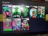
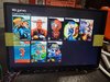
To see if it was not from the screen or the screen card I tested that the VGA works fine by plugging it into my laptop and it works fine :?:

Finally I hacked a black wii (RVL-CPU-50), installed BootMii in IOS with the Homebrew channel and installed BBloader with the VGA patch activated.
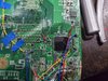
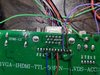
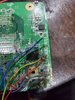
I soldered all wire for VGA with RGB color to be sure not to make a mistake in my connections :
(this is for test so it is an untrimed wii)
20200903_211803-2.jpg
20200903_211813-2.jpg


And after several tests I unfortunately do not have a VGA signal with this wii either :'(

I have no idea where it could come from, does anyone have the same problem ?
What can I do to try to resolve the issue ?
 
From what I can see, it seems you're missing 3.3V to mode. 3.3V to the mode pin is needed to force VGA instead of composite.

Annotation 2020-09-03 161726.png


You can take 3.3V from the right edge of FIL39 in this picture. Or from pin 10 as documented in the picture.
 
Thanks for you help,

3.3V is directly connected to my trimmed screen board on my portable with my trimmed Wii, the RCA work but not the VGA.
On my second test with the Untrimmed wii the screen board is the same but it is not trimed and powered by external 5V, of course I have connected the GND between the Wii and the screen board, so I don't need the 3.3V line.
 
Are you saying it's fixed now?

I might not be understanding you correctly, as the only portable I've completed is a GWii. To be clear, I'm saying you need to wire 3.3V to Via8 in the documentation of the picture I showed you. That is what is needed to force a trimmed Wii to output VGA with the VGA patch in BBLoader. I'm not saying you need to do anything else with the driver board. You need to wire 3.3V to the mode Via on the Wii. This is easily done by stealing 3.3V from the Wii itself with a single strand of magnet wire from Via10(3.3V) to Via8(Mode) in the documentation provided.
Annotation 2020-09-03 163737.png

In the picture you showed you don't have anything wired to the mode pin. This pic is what I assume is your trimmed Wii. As you don't have 3.3V to the mode pin you won't be able to get VGA output.

If I have misunderstood you and you get what I'm saying I apologize if this ^ comes off as rude. I might just not understand the parts in your portable.
 
Last edited:
Ahhhh :facepalm:
I understand,
I need to put 3.3V on Via8 (Mode) to make it work !
I had misunderstood, I thought you said that I had to take the 3.3V from here and connect it to my screen card :facepalm:
I also thought that this pin was already connected to 3.3V O.o

Thank you very much @waldie I will try this right away

PS : I really like your avatar kirby gif :D
 
Kirbo is indeed the best.

Lemme know if it works. If it doesn’t other trouble shooting tips would be as follows:

1. Make sure your wires are correct going to your driver board (I’ve never worked with your screen board so idk what goes where)
2. Test composite as it’s easier (make sure to remove the 3.3V to mode if you test this)

Not sure if you have tried composite yet. Just trying to cover all the possibilities.
 
Yeah it work !
Woow the VGA its very clean
Thank you so much @waldie
20200904_145538-2.jpg
20200904_145850.jpg

It work ... but the colors are strange :
20200904_172024.jpg


I inverted the green and the red :facepalm:
 
Last edited:
Yes, thank you @Aurelio :D
The pictures in the guide with the colored tracks are confusing since they are not the corresponding colors O.o

Now it work fine :
20200904_182303.jpg


I am impressed with the notable difference between RCA and VGA :D
This is really a big improvement, thank you very much for allowing this !
 
The pictures in the guide with the colored tracks are confusing since they are not the corresponding colors O.o
The traces color matches with the YPbPr component cable ones, which is the official output and the diagram was made back when VGA wasn't even a thing yet
 
Ah ok I understand better :D
Now that vga is more common, would it be a good idea to change the colors for it or put a disclaimer to prevent other people from getting it wrong ?
 
Eh. The documentation is pretty clear. All you really need to do is match the numbers to the via. Plus, if you mess up RGB it’s really obvious, you can easily just switch them up with no damage caused. So a disclaimer or change is unlikely.
 
The traces color matches with the YPbPr component cable ones, which is the official output and the diagram was made back when VGA wasn't even a thing yet
i doubt i get a response but my colors are off a lil. n i tripple check my wires to the right color pin. but im seeing mostly green even tho i see red n blue colors but what i think really should be blue is green. its confusing the heck out of me.
 
i doubt i get a response but my colors are off a lil. n i tripple check my wires to the right color pin. but im seeing mostly green even tho i see red n blue colors but what i think really should be blue is green. its confusing the heck out of me.
Pictures will help.
 
You've got them in the wrong order for VGA, literally the same mistake as OP. Read this thread from the top again.

lol. omgoodness im slow sometimes. could u plz just show on the pic the right correct wiring plz. it would be much appreciated. thats the last thing i need to have it fully functional and i can make my case tomorrow.
 
lol. omgoodness im slow sometimes. could u plz just show on the pic the right correct wiring plz. it would be much appreciated. thats the last thing i need to have it fully functional and i can make my case tomorrow.
Read the guides properly. Look at the numbers, not the colours.
av_encoder.png
 
omgoodness i see what u mean. 11 is marked blue but showing as red color. thanks again u r the greatest

yes yes yes its flawless now. thanks a million. for any1 who see this thread and have same problem i attached the correct color wire to the vias. thanks again wesk. u r the best.
 

Attachments

  • 16220047850544744884800423399065.jpg
    16220047850544744884800423399065.jpg
    4.2 MB · Views: 492
  • 16220048035478451073511737896402.jpg
    16220048035478451073511737896402.jpg
    2 MB · Views: 472
Back
Top