

LCandell
.
Knowledge:
-Dual What?
Dual Wi-fi Mod lets your console switch between custom firmware and original one.
-Why?
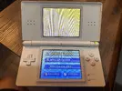
Once you flash a custom firmware on your Wi-fi module, your top screen gets unusable while using functions like screen-change buttons or video output, only seeing a yellow picture. This makes custom firmware only desirable for Gameboy Macros or single-screen consoles.
-How?
You must modify or install a mod on your Wi-fi module which lets you install both firmware by doing some electrical connections or buying a custom flex. The firmware can be swapped easily with a switch, doing a signal bridge to GND.
Credits:
Facelesstech for the original dual Wi-fi mod and his original flex. You can find the files and the flex method here:

 facelesstech.wordpress.com

 github.com
Tools and materials:
-Soldering Iron.
-Hot Air Gun (Optional).
-Soldering Wire.
-Multimeter.
-Tweezers.
-Small files.
-Precision knife.
-Wrapping wire, Magnet Wire or Copper conductors to make the connections.
-2 Wi-fi Modules for Nintendo DS (One without modification, one with CFW).
-Transistors:
-3pin/2pos switch (For testing).
-Flux (Your best friend while soldering).
-UV Solder Mask, Glue or Resin to protect the connections (Optional but recommended).
-Kapton tape or any heat resistant film to work over the module.
As you can see, I usually try to do DIY mods and builds aiming to use only soldering skills (without custom PCB designs and 3D printing)
And this time I'm glad to show you this worklog. Let's begin
1. Custom Firmware:
Again, you need to patch custom firmware on the wifi module (here's where the OS is installed), but I can't provide here the steps to do it.
Here's the official documentation about installing patch for TV Out mod:
 github.com
-You only need to install custom firmware on one of your modules.
-This step can be skipped because its easier to flash the module once it's finished (I didn't need to bridge SL1 contacts).
2. Preparing:
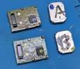
Remove the smaller metal covers from both modules to access the flash memory, you can place marks on the chips to identify them if you opted to flash before dismounting.
3. Wiring the circuit:
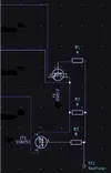
Here's the circuit schematic, which can be found on Facelessthech's files. You can copy this circuit shape if you want to keep the circuit as small as possible.
3. Building the module:
3.1. Use your preferred method to remove the flash chips from both modules (yes, both, you'll se why later). Also you can remove the capacitor without issue.
Place a kapton to protect the surface where you'll place the circuit, only in one module.
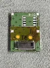
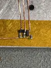
3.2. Place the circuit over the protected zone, in this step I tried to align the middle signal (of physical circuit) with the middle of the chip location, then solder the trace/wire to the indicated pad. Also you can use kapton over the components to keep the circuit in place temporary.
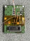
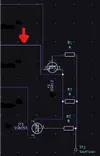
3.3. Protect the soldered trace with UV Resin.
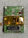
3.4. Use tweezers or a fine tool to carefully bent over the pin 6 of your chip (see the silk mark on the picture to identify polarity).
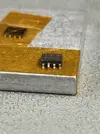
3.5. Place the chip over the module and solder the pins 1-5, 7-8 to the pads. Then solder the right signal (of physical circuit) to the indicated pin of the first chip.
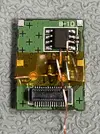
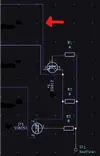
3.6. Place the second flash chip on mirror position. For example, you can place the second chip over the first one (check polarity), then flip the second chip to the left side, resulting in the same position as picture shows. Solder the four pins between both chips, being careful to not bridge the solder.
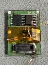
3.7. Protect the soldered pins with UV Resin, this will help to easily run the connections over both chips.
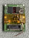
3.8. Solder the left signal (of physical circuit) to the indicated pin of the second chip.
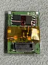
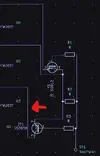
3.9. Run straight wires between the top and the next pin of both chips and solder them, resulting in the following circuit. Run the last straight wire between the lower pin of both chips and solder it. I've used magnet wire in this step to prevent the connections to short. Also you can protect the lower connections with UV Resin before placing the last wire over them.
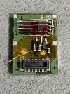
3.10. Remove the kapton that you placed to keep the circuit in position. Check continuity with multimeter to validate connections.
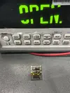
3.11. At this point, you'll only have one remaining connection coming from the resistors, bend the wire/trace and apply a few solder to prepare a kind of "pad". This pad will receive a GND signal form a switch to swap between both firmwares.
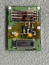
From this point, now you can connect your module to the console to run tests.
-Connect the module to your console.
-Turn on your console and check if can boot correctly.
-For the second chip test, solder a wire to the pre-shaped pad.
-Solder the other end of the wire to any GND location.
-Turn on your console and check if can boot correctly.
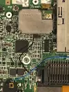
3.12. All connections are ready, but the new circuit won't let you place the metal cover again, so you'll need to modify it. Try to place the cover in place to see which tab you have to bent or remove.
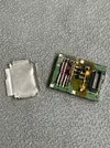
3.13. I've placed kapton inside of the metal cover to prevent the connections to short. This is a temporary fix because I'll fill the inside of the metal cover later with T7000 glue.
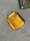
3.14. Finally I've used UV Resin to fully cover and keep the components in place, then installed the metal cover.
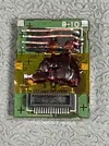
3.15. Now you have your module ready! Smaller and closer-look to the unmodified one.
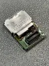
3.16. If you didn't flash the custom firmware before, boot with your desired chip and flash the custom firmware on it. I've personally selected the second one because my console will be used in handheld mode most of the time, if you want to do the same, repeat the steps...
-For the second chip test, solder a wire to the pre-shaped pad.
-Solder the other end of the wire to any GND location.
-Turn on your console and check if can boot correctly.
-Flash the custom firmware following the steps on section 1.
Now every time you hit the GND switch on, you can unleash the power of the custom firmware, adding features to your console.
Testing modules
Made the first module for @Cholost (aka GBA<3) thanks for testing my first work!!!
Then made my own module for my pokedex console
HOPE this works for you!
Be free to DM me if you want some help.
-Dual What?
Dual Wi-fi Mod lets your console switch between custom firmware and original one.
-Why?
Once you flash a custom firmware on your Wi-fi module, your top screen gets unusable while using functions like screen-change buttons or video output, only seeing a yellow picture. This makes custom firmware only desirable for Gameboy Macros or single-screen consoles.
-How?
You must modify or install a mod on your Wi-fi module which lets you install both firmware by doing some electrical connections or buying a custom flex. The firmware can be swapped easily with a switch, doing a signal bridge to GND.
Credits:
Facelesstech
for the original dual Wi-fi mod and his original flex. You can find the files and the flex method here:
DS Lite dual wifi chip -TV out
tl;dr The one thing that was lacking with the TV out mod on the DS Lite was the ability to keep the top screen. See when you apply this mod it turns the DS Lite’s top screen yellow. I did see…
facelesstech.wordpress.com
GitHub - facelesstech/ds_lite_wifi_chip_switcher: ds_lite_wifi_chip_switcher
ds_lite_wifi_chip_switcher. Contribute to facelesstech/ds_lite_wifi_chip_switcher development by creating an account on GitHub.
github.com
Tools and materials:
-Soldering Iron.
-Hot Air Gun (Optional).
-Soldering Wire.
-Multimeter.
-Tweezers.
-Small files.
-Precision knife.
-Wrapping wire, Magnet Wire or Copper conductors to make the connections.
-2 Wi-fi Modules for Nintendo DS (One without modification, one with CFW).
-Transistors:
- SS8050 NPN Transistor SOT 23.
- S9012 PNP Transistor SOT 23.
-3pin/2pos switch (For testing).
-Flux (Your best friend while soldering).
-UV Solder Mask, Glue or Resin to protect the connections (Optional but recommended).
-Kapton tape or any heat resistant film to work over the module.
As you can see, I usually try to do DIY mods and builds aiming to use only soldering skills (without custom PCB designs and 3D printing)
And this time I'm glad to show you this worklog. Let's begin
1. Custom Firmware:
Again, you need to patch custom firmware on the wifi module (here's where the OS is installed), but I can't provide here the steps to do it.
Here's the official documentation about installing patch for TV Out mod:
Lost-NDS-TV/fwpatch at main · LNH-team/Lost-NDS-TV
The Lost Nintendo DS Television Output, brought back to life - LNH-team/Lost-NDS-TV
github.com
-You only need to install custom firmware on one of your modules.
-This step can be skipped because its easier to flash the module once it's finished (I didn't need to bridge SL1 contacts).
2. Preparing:
Remove the smaller metal covers from both modules to access the flash memory, you can place marks on the chips to identify them if you opted to flash before dismounting.
3. Wiring the circuit:
Here's the circuit schematic, which can be found on Facelessthech's files. You can copy this circuit shape if you want to keep the circuit as small as possible.
3. Building the module:
3.1. Use your preferred method to remove the flash chips from both modules (yes, both, you'll se why later). Also you can remove the capacitor without issue.
Place a kapton to protect the surface where you'll place the circuit, only in one module.
3.2. Place the circuit over the protected zone, in this step I tried to align the middle signal (of physical circuit) with the middle of the chip location, then solder the trace/wire to the indicated pad. Also you can use kapton over the components to keep the circuit in place temporary.
3.3. Protect the soldered trace with UV Resin.
3.4. Use tweezers or a fine tool to carefully bent over the pin 6 of your chip (see the silk mark on the picture to identify polarity).
3.5. Place the chip over the module and solder the pins 1-5, 7-8 to the pads. Then solder the right signal (of physical circuit) to the indicated pin of the first chip.
3.6. Place the second flash chip on mirror position. For example, you can place the second chip over the first one (check polarity), then flip the second chip to the left side, resulting in the same position as picture shows. Solder the four pins between both chips, being careful to not bridge the solder.
3.7. Protect the soldered pins with UV Resin, this will help to easily run the connections over both chips.
3.8. Solder the left signal (of physical circuit) to the indicated pin of the second chip.
3.9. Run straight wires between the top and the next pin of both chips and solder them, resulting in the following circuit. Run the last straight wire between the lower pin of both chips and solder it. I've used magnet wire in this step to prevent the connections to short. Also you can protect the lower connections with UV Resin before placing the last wire over them.
3.10. Remove the kapton that you placed to keep the circuit in position. Check continuity with multimeter to validate connections.
3.11. At this point, you'll only have one remaining connection coming from the resistors, bend the wire/trace and apply a few solder to prepare a kind of "pad". This pad will receive a GND signal form a switch to swap between both firmwares.
From this point, now you can connect your module to the console to run tests.
-Connect the module to your console.
-Turn on your console and check if can boot correctly.
-For the second chip test, solder a wire to the pre-shaped pad.
-Solder the other end of the wire to any GND location.
-Turn on your console and check if can boot correctly.
3.12. All connections are ready, but the new circuit won't let you place the metal cover again, so you'll need to modify it. Try to place the cover in place to see which tab you have to bent or remove.
3.13. I've placed kapton inside of the metal cover to prevent the connections to short. This is a temporary fix because I'll fill the inside of the metal cover later with T7000 glue.
3.14. Finally I've used UV Resin to fully cover and keep the components in place, then installed the metal cover.
3.15. Now you have your module ready! Smaller and closer-look to the unmodified one.
3.16. If you didn't flash the custom firmware before, boot with your desired chip and flash the custom firmware on it. I've personally selected the second one because my console will be used in handheld mode most of the time, if you want to do the same, repeat the steps...
-For the second chip test, solder a wire to the pre-shaped pad.
-Solder the other end of the wire to any GND location.
-Turn on your console and check if can boot correctly.
-Flash the custom firmware following the steps on section 1.
Now every time you hit the GND switch on, you can unleash the power of the custom firmware, adding features to your console.
Testing modules
Made the first module for @Cholost (aka GBA<3) thanks for testing my first work!!!
Then made my own module for my pokedex console
HOPE this works for you!
Be free to DM me if you want some help.
Last edited:


