Question Help needed with my PS2 Ultra Slim Mod

Joined
Feb 15, 2026
Messages
7
Likes
4
Hello guys!

So I was following the forum after stumbling upon Tito's video for the PS2 Ultra Slim mod and I was hesitant to do this myself as I have little to no experience soldering and console mods. After doing some simple soldering on defective hardware I finally musterd up the confidence to buy all the necessary stuff to do the mod and went with the Remixed version of the PS2 Ultra Slim (the PS2 Ultra Slim Fusion by Mrak408) as I liked the way the PS2 was powered with a small PD charger.

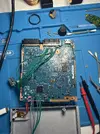
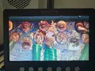
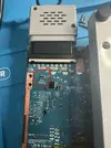
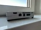
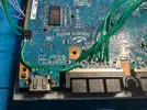
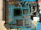
After messing up one SCPH 79k board (think I messed up something power related as the PS2 does not receive power anymore, left that board in a pile waiting to be troubleshooted), I bought a new one and just to give some context, those 79k's seem unobtainable in Europe but I did manage to find some after scouring the internet. This one I did manage to complete as you can see in the final picture. I took my time by testing the PS2 after each mod I did (USB-C PD, ElectronAnalog HDMI, internal MX4SIO) and everything seemed to work, until I buttoned up the case and plugged it into my TV, it did not power on anymore.

So these are my findings for now:
  • The PS2 received approximately 9V from the USB PD power adapter after probing several points on the board with a multimeter.
  • The PS2 turns on for a split-second and turns off.
  • During this speedy turn off, the PS2 draws 2 watts of power and sometimes more before it came back to 0 watts of power.
  • The BlueRetro controller adapter also turned on during this sequence as the LED was blinking.
  • I feel like something shorted itself out after I screwed the case back together but cannot find where.
  • There is a sound the console makes after I turn it on using the disc detection switch and if I bridge the wires manually, it also makes that sound (cannot upload video to show).
By the way, in the pictures, I used Kapton Tape to cover all the solder joints from bridging or shorting but these were removed to take pictures.
All help is welcome! I really do not want to spend another 80+ Euros on another PS2 :(
 

Attachments

  • IMG_4353.webp
    IMG_4353.webp
    272.8 KB · Views: 11
  • IMG_4356.webp
    IMG_4356.webp
    1.3 MB · Views: 12
  • IMG_4366.webp
    IMG_4366.webp
    3 MB · Views: 12
  • IMG_4363.webp
    IMG_4363.webp
    889.1 KB · Views: 21
Well done on giving it a go. The PS2 isn't the most difficult to set up, but there are a lot of contact points in a small area.
From what I can see, your wires are probably a little bit on the larger size, and the soldering is a little bit messy.

The ideal method would be to cut your wires, twist, and pre-tin them so you don't get 'whiskers' that can short things out.
Additionally, you should have nice, smooth, shiny solder connections. If it makes things easier, you can remove a bit of solder with some wick or a desoldering pump and replace with some fresh 60/40 lead solder. Make sure to use flux!
The existing solder oxidises over time, and fresh solder is an easy way to give it some life, but nothing beats using some good quality flux.

Since you've done the hard work of identifying the pins and soldering the wires, you're mostly there.
Get some good flux, resolder your wires (replace them with smaller gauge if need be), and make sure you have nice clean, non-hairy, connections.
Good luck!

EDIT: If you want somewhere specific to start with, I'd check out the two power wires and make sure there is no way they are touching. You can solder them parallel to the board first to make sure the connection is stable. Then move on to the 5V line on the Multi-out.
 
Nice looking unit!

Keep that other board and send some pics. Maybe we can get that one going too!
 
Nice looking unit!

Keep that other board and send some pics. Maybe we can get that one going too!
If this one works out, I will definitely! 79k models are expensive here so I want to keep it from the landfill. It will make a nice b-day present :)
 
Well done on giving it a go. The PS2 isn't the most difficult to set up, but there are a lot of contact points in a small area.
From what I can see, your wires are probably a little bit on the larger size, and the soldering is a little bit messy.

The ideal method would be to cut your wires, twist, and pre-tin them so you don't get 'whiskers' that can short things out.
Additionally, you should have nice, smooth, shiny solder connections. If it makes things easier, you can remove a bit of solder with some wick or a desoldering pump and replace with some fresh 60/40 lead solder. Make sure to use flux!
The existing solder oxidises over time, and fresh solder is an easy way to give it some life, but nothing beats using some good quality flux.

Since you've done the hard work of identifying the pins and soldering the wires, you're mostly there.
Get some good flux, resolder your wires (replace them with smaller gauge if need be), and make sure you have nice clean, non-hairy, connections.
Good luck!

EDIT: If you want somewhere specific to start with, I'd check out the two power wires and make sure there is no way they are touching. You can solder them parallel to the board first to make sure the connection is stable. Then move on to the 5V line on the Multi-out.
Thanks for the advice! I will take a look into it and report back as well! Appreciate the detailed response!
 
Thanks boss but I think I am still ways from solving my problem. Atleast the console turns on which is a relief but now the both controller ports and memory card slots do not work and for some strange reason, this spot on the board gets crazy hot (marked it on the attached picture). If I am not mistaken, this leads towards a short on some resistor right? However, on the microscope I do not see something burnt and I do not have a thermal camera to point it out.

After I managed to get the console up, I triple checked all solder joints for the MX4SIO mod and soldered them all again but alas, I managed to screw something up and for full transparency, I have attached another picture of the area. I was struggling to get fresh new solder on the console +3v3 pad and was also generous with the flux but during the process of removing some of the excess solder, I managed to rip a piece of the solder mask of the PCB.

I do not know if I am thinking into the right direction but at least the console is turning on which is already some progress.

Thanks again guys in advance!
 

Attachments

  • IMG_4371.webp
    IMG_4371.webp
    1 MB · Views: 15
  • IMG_4372.webp
    IMG_4372.webp
    3.7 MB · Views: 17
  • IMG_4370.webp
    IMG_4370.webp
    611.7 KB · Views: 12
Thanks boss but I think I am still ways from solving my problem. Atleast the console turns on which is a relief but now the both controller ports and memory card slots do not work and for some strange reason, this spot on the board gets crazy hot (marked it on the attached picture). If I am not mistaken, this leads towards a short on some resistor right? However, on the microscope I do not see something burnt and I do not have a thermal camera to point it out.

After I managed to get the console up, I triple checked all solder joints for the MX4SIO mod and soldered them all again but alas, I managed to screw something up and for full transparency, I have attached another picture of the area. I was struggling to get fresh new solder on the console +3v3 pad and was also generous with the flux but during the process of removing some of the excess solder, I managed to rip a piece of the solder mask of the PCB.

I do not know if I am thinking into the right direction but at least the console is turning on which is already some progress.

Thanks again guys in advance!
The component that is getting hot is the resettable fuse on the 3.3V rail. You have something putting a heavy load (high-impedance short) somewhere on your 3.3V rail. This is quite possibly caused by the shorting visible in the screenshot from your microscope.

Also, your 9V supply to the voltage regulator needs to be cleaned up.

It looks like you have all the right tools, but you really need to work on your soldering technique. Watch some YouTube videos of experienced people soldering and pay close attention to their process. I’m not trying to be mean — it’s just the truth.

Once the soldering is cleaned up, you’ll be able to troubleshoot more effectively. Right now, we can’t get past the soldering issues.

Here is my buddy Atheris, just watch how he does it.

Also Gusse

Just keep practicing on something else, not this console anymore, needs a break, lol!

You'll get it!!


1771288127387.webp
1771288338998.webp
1771288476207.webp
 
Last edited:
The component that is getting hot is the resettable fuse on the 3.3V rail. You have something putting a heavy load (low-impedance short) somewhere on your 3.3V rail. This is quite possibly caused by the shorting visible in the screenshot from your microscope.

Also, your 9V supply to the voltage regulator needs to be cleaned up.

It looks like you have all the right tools, but you really need to work on your soldering technique. Watch some YouTube videos of experienced people soldering and pay close attention to their process. I’m not trying to be mean — it’s just the truth.

Once the soldering is cleaned up, you’ll be able to troubleshoot more effectively. Right now, we can’t get past the soldering issues.

Here is my buddy Atheris, just watch how he does it.

Also Gusse

Just keep practicing on something else, not this console anymore, needs a break, lol!

You'll get it!!


View attachment 41736View attachment 41737View attachment 41738
I appreciate your honesty and do understand where you are coming from. Don’t worry, I won’t get it the wrong way because I know I have ways to go. It is inconsistent and that is just me being nice to myself. Thanks for all the resources, I will circle back once I have an update :)
 
Last edited:
Back
Top