
You are using an out of date browser. It may not display this or other websites correctly.
You should upgrade or use an alternative browser.
You should upgrade or use an alternative browser.
Worklog Booshman's N64 portable
- Thread starter Booshman
- Start date


The Amp is designed for push-buttons to lower/rise the volume (VUP/VDN). However, you could use these pots, if you connect them to the volume input - but they are mono!
Booshman
.
- Joined
- Sep 21, 2017
- Messages
- 150
- Likes
- 129
The Amp is designed for push-buttons to lower/rise the volume (VUP/VDN). However, you could use these pots, if you connect them to the volume input - but they are mono!
Hmmm, mono won't do. So one of these instead?

Could you fill me in on how to wire it? I assume VUP/VDN go to the outer posts of the posts on the pot and the centre is ground?
I notice the amp says 5v. Where do I connect it to, 7.4 or 3.3v?
- Joined
- Dec 16, 2016
- Messages
- 1,144
- Likes
- 2,868
- Location
- The Oregon Wildlands
- Portables
- just so many i am so cool
Hmmm, mono won't do. So one of these instead?
Could you fill me in on how to wire it? I assume VUP/VDN go to the outer posts of the posts on the pot and the centre is ground?
I notice the amp says 5v. Where do I connect it to, 7.4 or 3.3v?
You can run the amp off of 3.3v with no issues. Only difference I found when I powered it off of 3.3 rather than 5 was that the volume adjusted considerably quicker.
Booshman
.
- Joined
- Sep 21, 2017
- Messages
- 150
- Likes
- 129
You can run the amp off of 3.3v with no issues. Only difference I found when I powered it off of 3.3 rather than 5 was that the volume adjusted considerably quicker.
Could that be remedied with other components between the amp and the pot? As you might be able to tell, I'm quite lacking when it comes to electronics know-how, but something like this must be fixable.
Booshman
.
- Joined
- Sep 21, 2017
- Messages
- 150
- Likes
- 129
Some good news. My Superpad came in the post today!
In other news, I took some caps off the TFT driver board and reattached them with wires. This appears to have worked fine, other than screwing up anything with the colour red in it.


Anyone have input as to the issue? Are my wires too long?
In other news, I took some caps off the TFT driver board and reattached them with wires. This appears to have worked fine, other than screwing up anything with the colour red in it.
Anyone have input as to the issue? Are my wires too long?
Booshman
.
- Joined
- Sep 21, 2017
- Messages
- 150
- Likes
- 129
So I put the caps back to their original positions and the colour issue is still present. I assume something must have happened when I removed the caps with my heat gun. I used foil as a heat sheil to protect the areas I didn't want to mess with. Looks like a new driver board is needed.
Booshman
.
- Joined
- Sep 21, 2017
- Messages
- 150
- Likes
- 129
did you test the caps? You might have broken them, cause they don't really like heat at all.
No I didn't check them, not really sure how to go about that. Unfortunately in my haste, I've binned the board and ordered another, assuming it was dead, so I'll have to have another go. Any tip on how to try an relocate without frying the caps? I was very careful to only get them hot enough to be able to remove them, or so I thought.
- Joined
- Nov 5, 2017
- Messages
- 417
- Likes
- 506
Actually if the caps have their values written on the side of them (they usually do) you could replace them pretty cheaply.
I've seen this before on a NES that I repaired and it turned out to be a poor connection on one of the solders but it was far from obvious and the NES has a terrible AV board - now in saying that it could be a myriad of other issues so that's not a good thing to send someone on a goose chase with.
What's funny is that there is some of the red channel there, my suspicion would be on a component that has lifted slightly (possibly one of those tiny resistors) or an issue with the caps (as Nold suggested). The other thing with caps is if they're starting to die they might require a "warmup" period so if the picture improves after you leave it running for half an hour then you can be sure it's the caps that are the problem (although that's more something that 1980s consoles suffer from).
Booshman
.
- Joined
- Sep 21, 2017
- Messages
- 150
- Likes
- 129
Actually if the caps have their values written on the side of them (they usually do) you could replace them pretty cheaply.
I've seen this before on a NES that I repaired and it turned out to be a poor connection on one of the solders but it was far from obvious and the NES has a terrible AV board - now in saying that it could be a myriad of other issues so that's not a good thing to send someone on a goose chase with.
What's funny is that there is some of the red channel there, my suspicion would be on a component that has lifted slightly (possibly one of those tiny resistors) or an issue with the caps (as Nold suggested). The other thing with caps is if they're starting to die they might require a "warmup" period so if the picture improves after you leave it running for half an hour then you can be sure it's the caps that are the problem (although that's more something that 1980s consoles suffer from).
Well, as I mentioned, I trashed the board, so I need a new one. Shouldn't have been so hasty. I'll be sure to test the caps when I try again. Thanks for the input.


Booshman
.
- Joined
- Sep 21, 2017
- Messages
- 150
- Likes
- 129
That's so sharp we need to find a way to clone it before you bolt it all up! Methinks we've got an award contender here!
Haha, thanks for the praise, glad you like it.
I have a new driver board for the screen coming, and I want to get extra caps in case I need to replace the ones I remove. Could someone tell me how important the letters on the caps are. I have 2 with VT, and one with CK. I've looked online and I'm still unsure. Can I buy through hole versions which appear to have no letters, as long as the uf and voltage are a match, or do they need to be the exact same surface mounting cap down to the lettering? I'm struggling to find a cap with a CK marking that has the same rating as the one on the board.
- Joined
- Nov 5, 2017
- Messages
- 417
- Likes
- 506
I'm no expert in this so I'd ask anyone to please correct me if I've said something wrong - I've no tertiary training in electronics. Also forgive me if it sounds like I'm talking down to you I just don't want to give mis-guiding advice that could screw up a project! OK disclaimer over ")
I'd worry about replacing them when the relocation doesn't work - odds down you might never have a problem with that again. Now it only just occurred to me that you could have had two of the caps swapped when you re-wired it, or perhaps had one reversed - it's a super easy mistake to make that I've done on numerous occasions. I really should apologise that I only thought of this now, which makes me a terrible friend Photograph both sides of the board before you do anything with it as it can be invaluable later when trying to troubleshoot.
Disclosure complete, having done a quick search for CK and VT it'd appear they're both electrolytic, so they will have a "direction", This is also important when wiring back up - the positive side of these caps is the one with chamfers on it. That all said replacing caps is a matter of getting the correct type, and correct faraday rating, and equal (or higher) voltage. The good news is that if the caps are wrong they'll simply blow up, or the board won't work, but I've never had a board damaged from installing the wrong cap.
It did, however, scare the living shit out of my partner when one exploded - and that was totally on me wiring it up wrong.
I'd worry about replacing them when the relocation doesn't work - odds down you might never have a problem with that again. Now it only just occurred to me that you could have had two of the caps swapped when you re-wired it, or perhaps had one reversed - it's a super easy mistake to make that I've done on numerous occasions. I really should apologise that I only thought of this now, which makes me a terrible friend
Photograph both sides of the board before you do anything with it as it can be invaluable later when trying to troubleshoot.Disclosure complete, having done a quick search for CK and VT it'd appear they're both electrolytic, so they will have a "direction", This is also important when wiring back up - the positive side of these caps is the one with chamfers on it. That all said replacing caps is a matter of getting the correct type, and correct faraday rating, and equal (or higher) voltage. The good news is that if the caps are wrong they'll simply blow up, or the board won't work, but I've never had a board damaged from installing the wrong cap.
It did, however, scare the living shit out of my partner when one exploded - and that was totally on me wiring it up wrong.
Booshman
.
- Joined
- Sep 21, 2017
- Messages
- 150
- Likes
- 129
I made sure to quadrouple check the caps before. They were definitely in the correct orientation. I took some snaps before I began to make sure I had a reference later.
I just got the new board in the post and the caps which had VT are labeled d5 on this board. And the one that was CK is VT, so I assume the letters are unimportant and interchangeable.
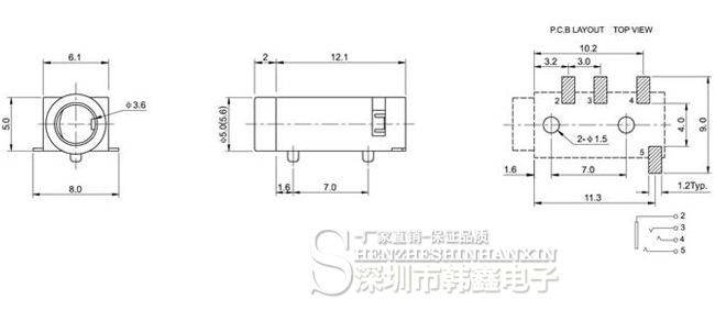
Another thing I'm unsure about is the headphone jack. I got a small one with 4 pins labelled as stereo. All the stuff I'm buying has descriptions in Chinese, but it definitely says stereo. From the reading I've done, am I correct in thinking that with it being 4 pins, it will be stereo to the headphones, but only mono when run off to a speaker? If someone could let me know if I'm right I would appreciate it, as if I need to replace it with a 5 pin jack, I will have to modify my case to accomodate it. Obviously something I'd rather avoid if I can. Here is the schematic from the sales page.
Apologies for all the questions. I really don't like to feel like I'm having my hand held as I build. I just really want to be sure what I'm doing.
Edit: Additional info. I'm a fucking idiot!

Just got the new driver board working. It was initially the same colour as the last time. I checked the N64 on the TV with composite and scart, same deal. Turns out that the RGB mod I did had bridged the red and green channel. When I say bridged, I could barely even see it held up to the light. I scraped the the edge of the solder with a knife and the colour came back. I initially checked to see if there was a picture after the RGB mod, but didn't try any games. With the first screen being blue and yellow the issue wasn't apparent until I put a game on after relocating the caps.
I just got the new board in the post and the caps which had VT are labeled d5 on this board. And the one that was CK is VT, so I assume the letters are unimportant and interchangeable.
Another thing I'm unsure about is the headphone jack. I got a small one with 4 pins labelled as stereo. All the stuff I'm buying has descriptions in Chinese, but it definitely says stereo. From the reading I've done, am I correct in thinking that with it being 4 pins, it will be stereo to the headphones, but only mono when run off to a speaker? If someone could let me know if I'm right I would appreciate it, as if I need to replace it with a 5 pin jack, I will have to modify my case to accomodate it. Obviously something I'd rather avoid if I can. Here is the schematic from the sales page.
Apologies for all the questions. I really don't like to feel like I'm having my hand held as I build. I just really want to be sure what I'm doing.
Edit: Additional info. I'm a fucking idiot!
Just got the new driver board working. It was initially the same colour as the last time. I checked the N64 on the TV with composite and scart, same deal. Turns out that the RGB mod I did had bridged the red and green channel. When I say bridged, I could barely even see it held up to the light. I scraped the the edge of the solder with a knife and the colour came back. I initially checked to see if there was a picture after the RGB mod, but didn't try any games. With the first screen being blue and yellow the issue wasn't apparent until I put a game on after relocating the caps.
Last edited:
Hey, we've all been there. I had a screen I used once with capacitive touch buttons, and I couldn't figure out for the life of me how to wire them up to work with tact switches. I literally hot glued the remote control right next to the button PCB with the IR LEDs facing each other and wired the contacts from the remote to the switches. Fried the remote in the process and had to order an entire other screen ($90!!) just to get another. It happens.
Anyway, vis a vis the headphone jack, you'll be able to wire it up just like a normal jack. Just bridge the two middle contacts or use the one second from the end for your R audio.

Anyway, vis a vis the headphone jack, you'll be able to wire it up just like a normal jack. Just bridge the two middle contacts or use the one second from the end for your R audio.
WELP. I didn't think to suggest checking the N64 for shorts...... at least it's working now. Did the new driver board set you back much?I made sure to quadrouple check the caps before. They were definitely in the correct orientation. I took some snaps before I began to make sure I had a reference later.
I just got the new board in the post and the caps which had VT are labeled d5 on this board. And the one that was CK is VT, so I assume the letters are unimportant and interchangeable.
Another thing I'm unsure about is the headphone jack. I got a small one with 4 pins labelled as stereo. All the stuff I'm buying has descriptions in Chinese, but it definitely says stereo. From the reading I've done, am I correct in thinking that with it being 4 pins, it will be stereo to the headphones, but only mono when run off to a speaker? If someone could let me know if I'm right I would appreciate it, as if I need to replace it with a 5 pin jack, I will have to modify my case to accomodate it. Obviously something I'd rather avoid if I can. Here is the schematic from the sales page.
Apologies for all the questions. I really don't like to feel like I'm having my hand held as I build. I just really want to be sure what I'm doing.
Edit: Additional info. I'm a fucking idiot!
Just got the new driver board working. It was initially the same colour as the last time. I checked the N64 on the TV with composite and scart, same deal. Turns out that the RGB mod I did had bridged the red and green channel. When I say bridged, I could barely even see it held up to the light. I scraped the the edge of the solder with a knife and the colour came back. I initially checked to see if there was a picture after the RGB mod, but didn't try any games. With the first screen being blue and yellow the issue wasn't apparent until I put a game on after relocating the caps.