Worklog Ashida Worklog! (My First Wii Portable)

Nolak

.
Joined
Jul 9, 2023
Messages
7
Likes
10
Hello :)

I finally have all of the parts that I think are needed for my Ashida! I am going to post my worklog here as I always love reading other people's and find them useful for learning.

I have gotten a case resin printed from PCBWAY in transparent, and it is really nice. I also ordered some chrome gold buttons from an eBay seller but am unsure if I am going to use them yet as the B, X, and Y buttons are a bit too big for the case. I have also decided to harvest parts from a Smash Ult GCC, so I have OEM buttons if I desire. I also have a backup Wii just in case I mess up.
1689810618778.png

As of now I have softmodded the Wii and taken it apart to get to the motherboard (and it still boots!).
1689810545517.png

I am excited to get started on this project!
 
So...
I have just trimmed my Wii and have sanded it. I am unsure if I did it all correctly.

Edit: Felt like I needed to add. I did a standard OMGWTF trim but I decided to trim it similar to how Ginger did in his recent trimming tutorial, in which he kept in a screwpost and cut an edge near the video output.

For sanding I went with 100, 220, 320, 400, 600, and then 1500 (probably not the best to go straight up to 1500 but I figured it could maybe help since I had it). The edges are all smooth to touch, with the exception of the areas where there are cut vias. For the most part I sanded at a 90-degree angle, which I now realize could be a possible issue.
1689907335661.png
1689907348514.png
1689907320284.png

Additionally, I had a couple places where I accidentally made flaws on the board. I have asked in the discord about most of these and was told it should be okay, but I will post here just in case they affect anything (such as my 3.3v resistances). I have included two photos each, one with light and one without.
1689910959545.png
1689910987530.png

1689911077734.png
1689911112192.png

1689911159103.png
1689911164438.png

1689911199002.png
1689911189937.png

1689911223968.png
1689911229915.png


Also, I tested the resistance, my chart is below.
1689910239584.png

Unfortunately, it seems that all of my voltage resistances are fine except for 3.3v! I have seen for a quick second on GND to 3.3v stating a value of 7._k Ohms, but it was really quick. I do not know how I messed this up, but I really hope that it is fixable. I have a feeling it could be an issue with my sanding, but it could be anything.

I have posted these pictures with hopes that anyone more experienced than me can point out flaws I have done.
 
Last edited:
You've cut through/hit a few components along the trim edge. I'd remove them and check again.
Also you have some visible layer curling along the edges of your trim.
1690081421526.png

That shit needs some 200 and 400 grit to break up
 
It's been a year since my last post here, and I have not worked on it much more since then until recently!
In August 2023: I decided to work on the front half of the Ashida. I assembled the controller PCBs and that was pretty much it.
1723010251391.png

Since then, I decided to purchase the DD because I believe it will make the portable nicer when I finish it.

However, despite the progress I made to the front, the Wii that I was working on still had 3.3 shorted to ground. Luckily, though, I had a second Wii. I started work on this Wii today and got good voltage readings!
1723010413909.png

After this, I decided it was time to test the Wii. This is where I now face problems.

With my current wiring setup, the Wii seems to turn on; the Wii gets hot overtime and if I connect the wires for the fan it starts to spin. However, I do not get video output onto a tv. Additionally for reference, I am using the Ashida interface board with the switch slide as a button to power on the Wii and that seems to work: the fan turned on when I flipped the switch on while a battery was in and the Wii processor started to heat up. Despite this, the Wii still fails to display a video signal. Also, for reference I did not enable VGA on this Wii.
1723010589648.png
1723010617246.png

Now, I hope that the issue at hand is really just a simple one related to my wiring; perhaps I forgot to wire something into the right place? I believe that the most likely places for the fault could be related to my component wiring or maybe even the video chip itself. While trimming I did hit a small area on the back near the location where video and audio is able to be rewired to, so maybe the issue could be on the Wii itself? Below are a couple photos of some of my accidental hits with the Dremel and a close-up photo of my soldering to the U10 via just in case that was an issue.

1723011076227.png

1723011124597.png
1723011028334.png


If anyone would be able to help with this issue that would be fantastic! I will continue to try to troubleshoot this tomorrow, but in the meantime if anyone would be able to help lead me in the right direction that would be appreciated.
 

Attachments

  • 1723010615069.png
    1723010615069.png
    20.3 MB · Views: 132
Finally came around to working on this project again, and I'm ALMOST finished.

I tried many things to try and get my second Wii trim to work, but nothing worked so I ended up trimming a third Wii, and that worked! So, I was finally able to build the Ashida.

The last time I was able to test the Wii was after installing my PMS lite, PMS PD2, and parts of my audio peripheral board. I was able to get composite video on a tv which booted into RV loader and read my USB and games on it. Since, I haven't tested the Wii on composite since installing audio, controller, and the DD.
1767995413279.webp

At this point, I have everything built (except mx and bluetooth), yet I don't get video signal on my screen, and the screen doesn't turn on. The fan turns on and I believe it is sensing the thermistor as it starts high before becoming weak. The LED doesn't turn on, but didn't turn on in my initial tests either (I'm not sure if it's supposed to or not until I activate it in RVloader?) The biggest thing to stand out to me is that the 1.8v line reads at around 1.24v when the Wii is powered on. The resistance between ground and 1v8 is normal, at around 36.3 ohms. The resistance between 3v3 and gnd is a little weird, initially reading at around 1k ohms, shooting to no reading, and then shooting to around 5k ohms before slowly steading at 2.59k ohms. Not sure if that is normal or not.
1767995458072.webp

I've done a little bit of testing to try and fix this issue, but nothing has solved it yet. There is likely some kind of short in my DD flex, but I'm having a tough time removing it with solder wick so I can see if the Wii still boots without the DD connected. I have yet to remove other wires such as D, C, WS, MC, etc and test to see if the Wii still works. However, I had a little bit of a scare today when testing after disconnecting my screen. My battery started smoking as I put it in my Ashida. I suspect that this happened because I have done a lot of adding and removing of the battery, which ripped the wrapping on the battery off over time which caused the metal side of the battery to make contact with B+, creating the smoke. Luckily, I was able to remove the battery quickly and the case suffered minimal damage. My B+ wire to the PMS was desoldered in the process. Afterwards, I used my other battery to test if the build performed any differently after the incident and everything is the same as before, resistances, voltages, and my fan. I believe I got lucky here and didn't fry anything as the battery wasn't fully in the slot when this incident occurred.
1767995516386.webp
1767995524441.webp

What I'm asking for advice on:
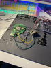
I've provided photos of my build and the battery incident. I have a plan moving forward to disconnect components and see if I can fix my 1v8 reading. However, I request if anyone notices anything that could be causing issues that I haven't noticed yet. I'm also asking if anyone has any tips for me to test whether or not my DD is causing these issues/if there are shorts there. I've done resistance readings between the vias on the flex, and nothing seemed to be shorted to each other from those readings, but I may be wrong. I'm having trouble actually removing the flex from the vias, so some tips on how to do that could be appreciated. Lastly, I want to make sure that this battery incident doesn't happen again. My battery wrappings were slowly worn over time from taking them in and out of the console, and I'm wondering if there are any other measures of disconnecting the battery that would prevent this. Is it possible that I could keep the battery in the holder, and simply solder and unsolder my red B+ wire from the battery clip when I'm testing? I've asked for a little help in the discord and got some help on the testing process yesterday. I've come here to have a place to store all of my information and update on the battery incident. Please let me know if anyone has input on this, but I'll be testing more in the meantime, I'm just very scared now after that battery incident! I'm happy to provide more photos and information. Thanks!
 
A little more to add.

I'm still able to charge my one working battery with my PMS PD2 and my USB is read when plugged into my computer via USB-C. It stops being read when I flip the switch to "turn on" the Wii. I think this is another sign that my PMS isn't fried from the battery damage.

I disconnected WS, D, C, MC/GND, L/R+/-, GCD, SCW, SDW, DI, and CK (everything new I added since my last test except for the DD flex vias) and still have a reading of 1.24v on the 1v8 line. This leaves, assuming I didn't mess up something that I built before my last test of the Wii, the DD flex vias as the most probable area of a short. I'm still having trouble desoldering the flex. I've tried to use lots of flux and resolder all of the vias in attempt to fix a short but that hasn't helped. I suspect it's possible that I've shorted to another via beneath the flex isn't used by the flex, since I accidentally removed the solder mask off of a couple extra vias before installing the flex. I want to confirm that the DD is the area of the short by testing composite video after removing the flex but am having trouble removing the flex. What's the best way to do that?
 
Was able to disconnect my DD flex. The Wii turns on again when connected to composite.

Issue is 1.8v is STILL read at 1.24v. I get video signal and can play games despite this low voltage.

I've confirmed this reading at multiple vias and test points, including TP2. I'm able to connect my controller from the front side of my case and play Mario Kart and Animal Crossing. I was able to complete a full race in Mario Kart and play a replay of the race. The CPU seemed normal, but I'm not all too familiar with this mk game. Additionally, my audio doesn't work and my d-pad, b button, and my triggers don't work either. This could be related to this voltage or could be a simple wiring issue with my gc+2 or uamp2. I haven't looked enough into that yet.

Is it possible that I undervolted my Wii? I've read a little and saw that Wesk was able to undervolt 1.8 to 1.18v, so 1.24v is possible to run the Wii at. I have no clue how this would be possible though; I'm not too familiar with this. My LDO is managing the 1.8v line so it would be a problem with the Wii and not my PMS. The alternative is I somehow shorted 1.8v somewhere to 3.3v, but again I don't know how/where that would happen. I'm not sure if I need to fix this issue or not before attempting to complete the Wii again. I'd imagine the more likely scenario is I have a short and need to fix that so I can regain controls and audio.

I'm going back to uni tomorrow so won't have access to a crt anymore for tests but have a week before classes start so I can continue working on troubleshooting. I think moving forward I'm going to wire my DD without the flex strip as I had issues before with that and broke a pad on the strip. Would love any comment on this.
 
Back
Top