
The Wii SPii
By StonedEdge
The Wii SPii is now open source! I've had the chance to test everything thoroughly (the newer Rev 1.4 PCBs) and feel confident enough to allow others to at least have a go at building their own WiiSPii using the Joycon board (3DS slider PCB will be released here at a later date when I've had a chance to test and assemble that board). I take no responsibility for any assembly errors or mistakes during the build process. Before you attempt to build it, know that I struggled due to the fine pitched soldering required and the limited amount of space to work with. This is not beginner friendly at all, so don't try this for your first ever build if you don't know what you are doing.
Description
The Wii SPii is an open source, portable Wii project. It uses real Wii hardware with no emulation and lasts around 2.5 hours on a full charge. This repository includes includes code from several contributors to the hobby (Aurelio, Gmanmodz and Jefflongo), CAD files, gerbers for main PCB ordering and a BOM of parts for assembly. The main build worklog can be found here.
Code
The code used in this project is based on the RVL-PMS (Gman), GC+ 2.0 (Aurelio92) and STUSB4500 (jefflongo) source code from below contributors, with minor tweaks being made to suit my project needs. All credit goes to contributors and I take no credit in their work whatsoever. I simply took their contributions and made slight changes, and am grateful for their genoristy and knowledge in helping me acheive the goals of this project. The project code is in the form of an MPLAB X project and can be compiled using MPLAB X IDE with XC8 compiler. Alternatively, you can also use the pre-compiled program (.hex) to program the PIC16LF15324, PIC16F15324 and PIC18F25K42 with MPLAB IPE. The microcontrollers were programmed using a PICKit 3. The only code that you will need to adjust and then compile is the lines 71-74 Lmin, Lmax, Rmin and Rmax configuration values in config.c, in order to scale the analog triggers to the correct values after reading the initial ADC values when the triggers are depressed and pressed. Set lmix and rmin based on depressed values, and rmin rmax based on pressed values of the ADC.
CAD
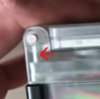
The case was designed with CNC manufacturing in mind and can be machined with little issue. I may include the toolpathing files at a later date, but not sure about that just yet as they are very specific to the machine used. The only modification required to get the hinges to fit will probably be filing down the holes. They are an extremely tight fit and designed for CNC, not FDM. FDM printers will usually shrink the size of holes, resulting in the hinges not fitting. I have uploaded both the .STEP (coming soon) and .STL files so that people may easily make changes to the model in their CAD software of choice, or simply print the case on any 3D printer. Prototypes were made on the Prusa i3 MK3s FDM printer and the final design was completed on a 3-axis CNC machine in acrylic plastic. I will not be taking any requests for CNC cases, so please do not ask me.
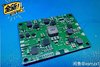
PCB/Schematics
The PCB is a 4 layer PCB ordered from JLCPCB. The PCB can also be ordered from OSHPark or PCBway, however due to increased cost for 4-layer PCB, I would recommend ordering directly from JLCPCB for quick turnaround time. A stencil is also required for ease of assembly along with solder paste and hot air to assemble the boards. I made a 3D printable stencil jig that can be used for easy placement of the stencil and PCB that I have included within the CAD zip files. The schematics will be uploaded at a later date. For now, I have just uploaded the gerber files.
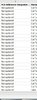
BOM (Bill of Materials)
These are the required components you will need to build the Wii SPii. This includes the PCB itself, PCB components and other peripherals required to make the console. This is simply the BOM for the PCB only, no other parts are listed. The screen is the 640 x 480 3.5" VGA panel everyone uses now from Aliexpress. It's driver board needs to be modified to use a custom xtal and smaller 10uH inductor for the backlight boost circuit. The driver board also needs to have its voltage rails powered directly via the AIO board for it to fit in the screen halves. The build requires a LMAO trim at minimum and requires a NAND relocation. You'll need two original GBA SP hinges or aftermarket hinges will also work, although not as good.
Contributors
I'd like to thank these people in no particular order for the awesome work you have done to help me complete this project. I feel like I cheated a little bit thanks to all of your hard work for this project, so the WiiSPii definitely feels like a collaboration rather than my own individual achievement. Thank you everyone!
- Dmcke5 for helping me re-model the WiiSPii for CNC machining, CNC machining the case out of acrylic and of course the hours and hours of phone calls back and forth over the past few months. Thanks for putting up with my numerous questions on CNC
- Gman for providing the community with countless hours of research and sharing his code to allow me to make some small modifications to the LED interface and audio amplifier
- Aurelio for GC+ 2.0 and BBloader Wii GUI contributions and updates, as well as helping optimize the LUTs for the analog triggers. Is there anything that GC+ 2.0 can't do?
- robertlong13 for assisting in the PIC16LF15324 ADC modifications for using 10K pot for volume control over i2c
- JeffLongo for his STUSB4500 code revisions
- YveltalGriffin for suggesting various hardware changes and reviews to PCB/schematics
I definitely want to learn to write my own code in my next project. Although I am really grateful for the open sourced projects, I plan to try and write my own code for all my future projects from now on.
If you have been paying attention on Discord you will know my pain, but this build is not an easy one. With that said, I hope you enjoy and very best of luck with the build!
Attachments
-
6.3 MB Views: 523
-
695.1 KB Views: 474
-
21.9 KB Views: 606
-
1.1 MB Views: 413
-
449.3 KB Views: 411
Last edited:
")