Following the death of my GC portable, I will not let my first portable go unfinished. This portable will be designed similarly to how I wanted the GC portable to be, but with improvements such as it being a Wii and adding an additional 2 batteries. I will not be using a PowerMii for this build because I still have regulators and a charger which I would prefer not go to waste. Unfortunately I will not be submitting to the contest this year because I'd rather put out the best product I can rather than rush to enter. It's a bit of a bummer but I'll be satisfied with how this portable turns out in the end. The goal is to have a minimal compromise portable. This portable will consist of:
Update 1 (5/27/17)
Update 2 (7/14/17)
Update 3 (7/15/17)
Update 4 (7/16/17)
Update 5 (7/19/17)
Update 6 (7/25/17)
Update 7 (8/29/17)
Update 8 (9/22/17)
Update 9 (10/3/17)
Update 10 (11/16/17)
Update 11 (12/6/17)
Update 12 (12/30/17)
Update 13 (1/3/18)
Update 14 (1/4/18)
Complete! (1/21/18)
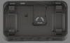
- ZN 40 case
- 4 18650 batteries
- 4" screen
- Composite out
- 4 internal controller ports (with a switch between internal and external p1 controls)
- Charge and play solution
Update 1 (5/27/17)
Update 2 (7/14/17)
Update 3 (7/15/17)
Update 4 (7/16/17)
Update 5 (7/19/17)
Update 6 (7/25/17)
Update 7 (8/29/17)
Update 8 (9/22/17)
Update 9 (10/3/17)
Update 10 (11/16/17)
Update 11 (12/6/17)
Update 12 (12/30/17)
Update 13 (1/3/18)
Update 14 (1/4/18)
Complete! (1/21/18)
Last edited: