
Ethan
.
- Joined
- Apr 20, 2019
- Messages
- 39
- Likes
- 37
Hello all its that time again where I attempt to learn to document my work.
The Plan
a clear Gwii
Black PCBs
minimal, but all white wiring
lots of patience
I have built a few Gwiis now but wanted one to keep for myself something special
Gman posted the glass gwii for sale and it was gone so fast but looked so good
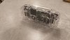
so a week or 2 later this showed up
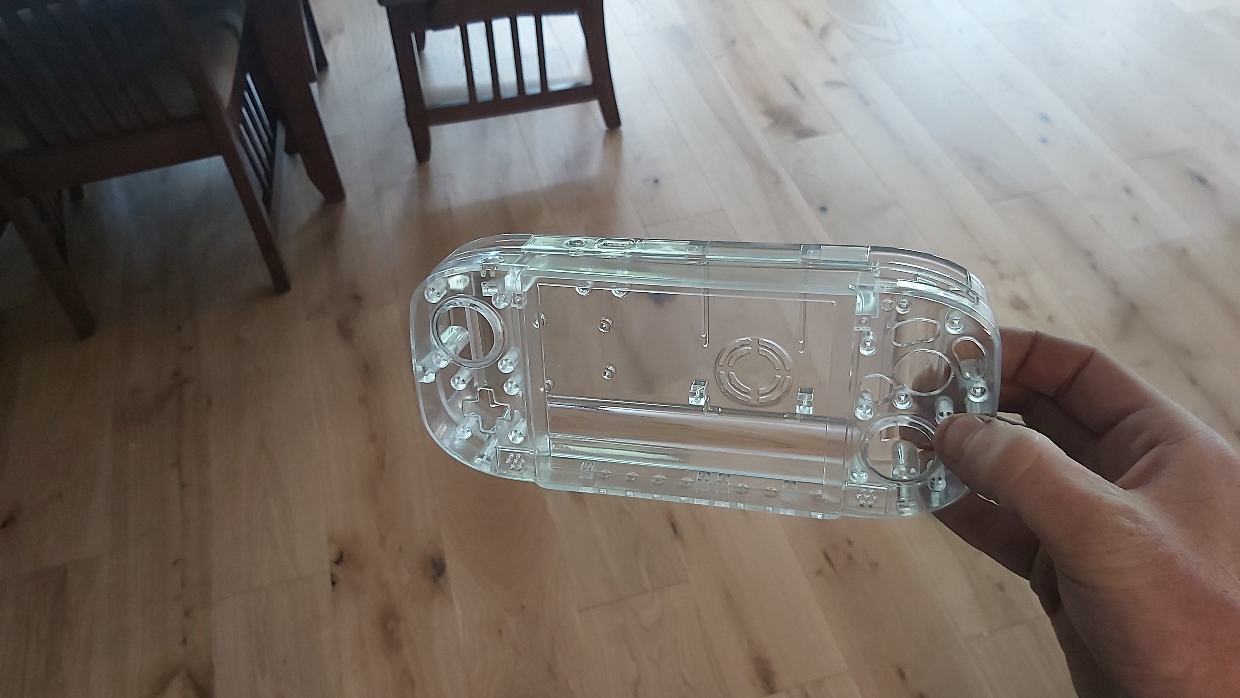
this is the same options as Gman used from PCBway
its called UTR-8100 (transparent)
(Sorta) Day 1 of work
it appears to be a bit brittle when a tried a screw carefully so I haven't dared to put any screws very far in yet,
to remedy this I ordered an M2 tap and a corresponding size drill to cut threads for the m2 screws and avoid stripping them all out
SIDE NOTE (high quality wire") )
)
I already had some white 30awg silicone rubber wire, but I had to yet to find some thicker stuff for the power wiring.
I ordered some and it arrived today
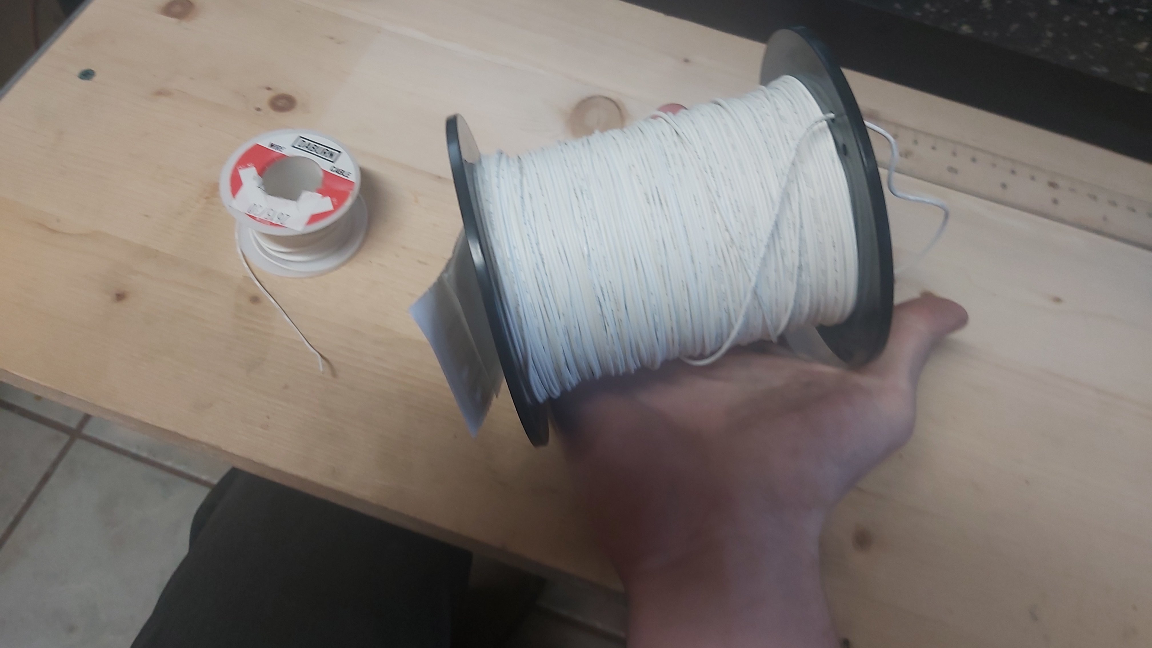
i guess 500ft of the (thicker stuff) will do
also
for others to note, i stuck with 24awg since its what i've always used and 22 was about 2x the price
although maybe 500ft was a little excessive
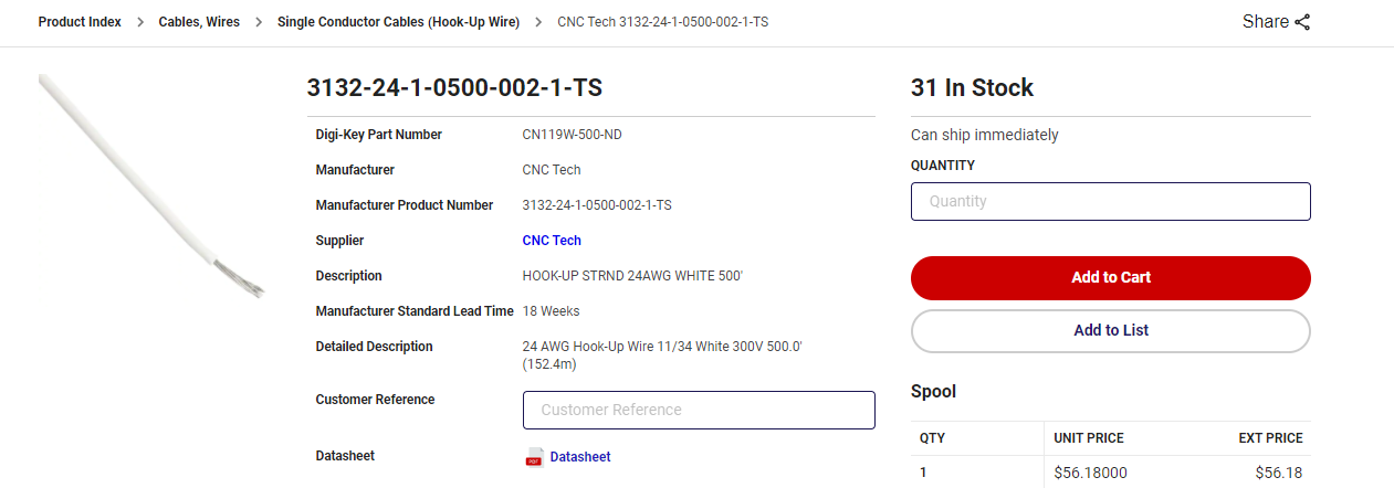
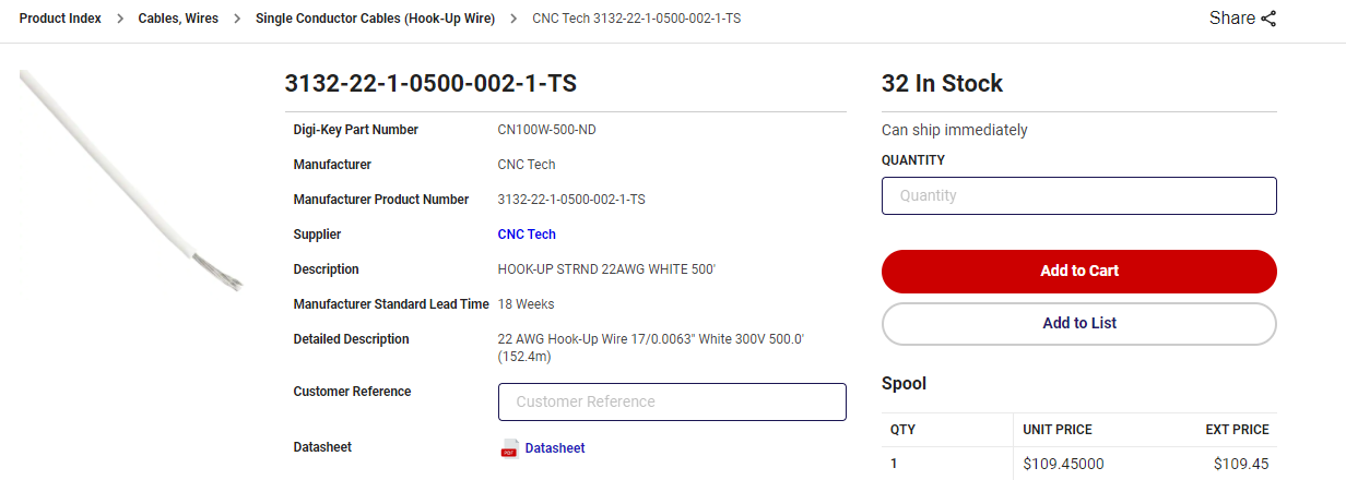
either way I love this wire its super flexible easy to strip and doesn't burn or melt when being soldered to.
(Sorta) DAY 2
to go with the nice clear case I needed to have some nice black PCBs
in my previous build log i showed off my custom GC breakout boards for the gwii and here im building on those. they remain mostly the same though
changes include
1. all PCBS in black now
2.Screen control button board works for black and blue driver boards
3. best for last new PCB to eliminate most of the upper wiring
Screen control board has to sets of resistors to be configured for the BB store blue driver board or the eBay special black one
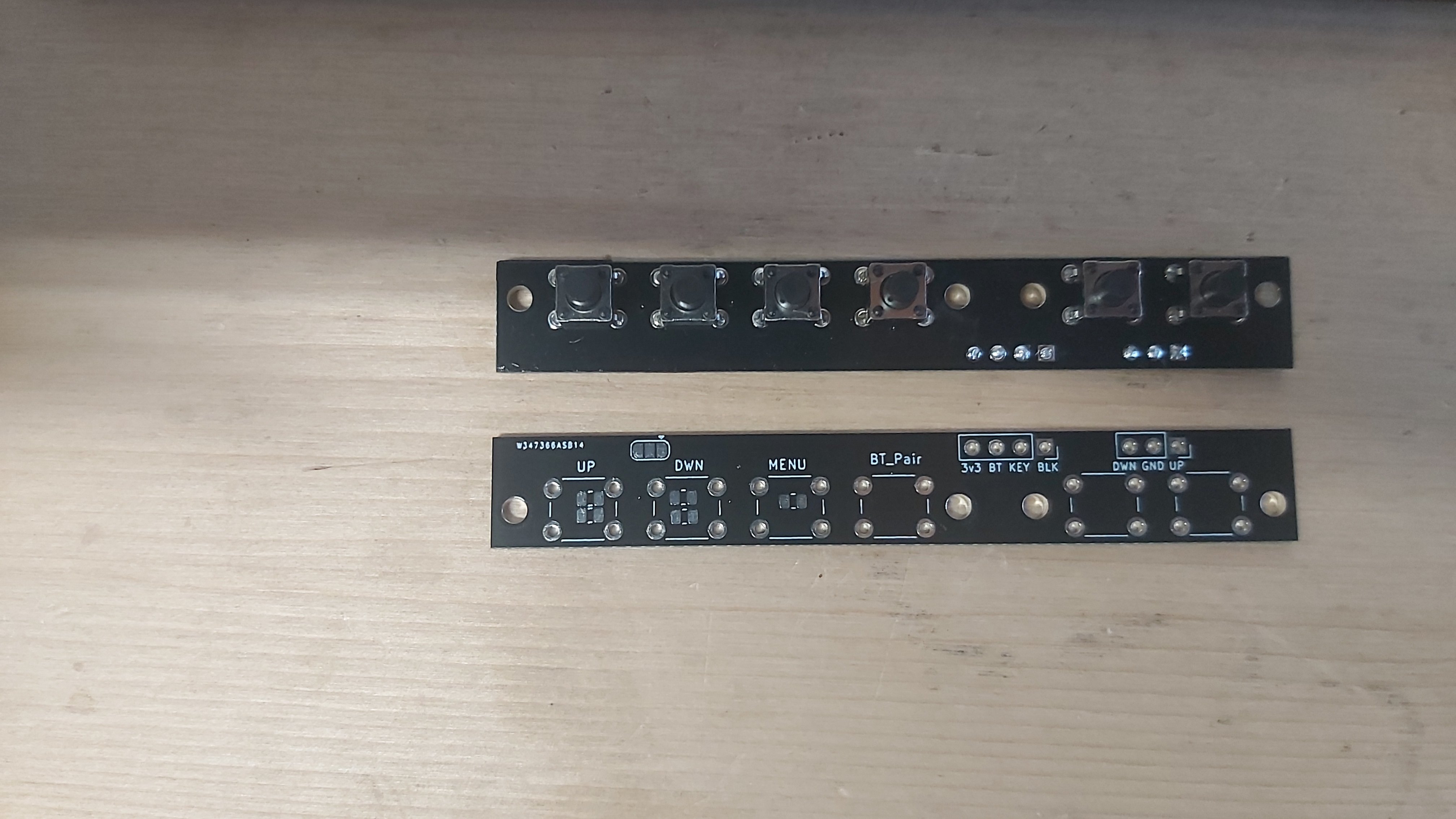
some of the labels are wrong and I forgot to label the jumper pad which selects the blue driver board or black driver board configuration
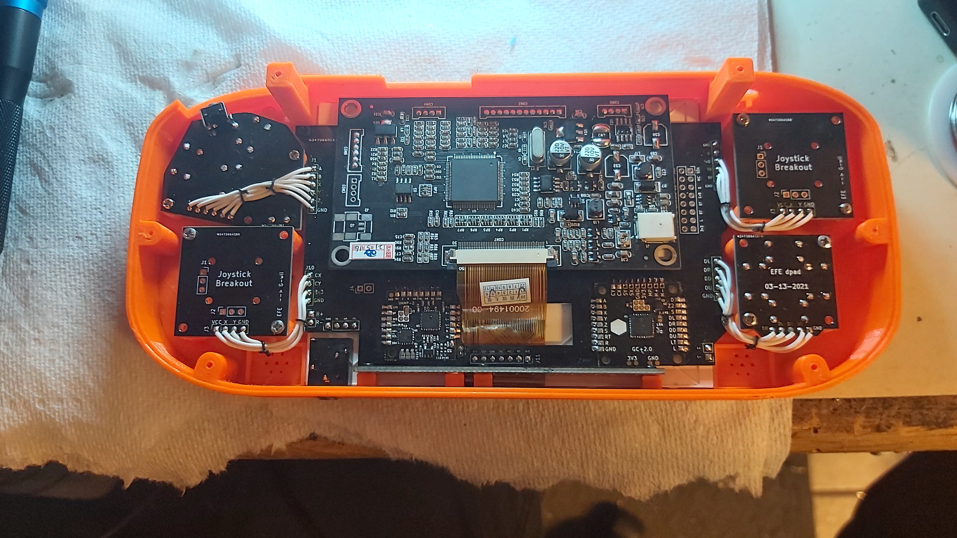
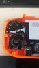
Here are some pictures with the GC+ and U amp mounted as I did the first wire up (I have it in a spare orange case to avoid damaging the precious clear shell)
the goal with the big PCB was to reduce the top screen clutter of wires and have almost all of the wiring between haves solder to one spot on the board
I kept the RGB hv lines out cause i don't wanna have any signal losses that could come from being to close to other lines
the Ump i2c lines and GC data line are though so ill have to see if they work well or have any issues
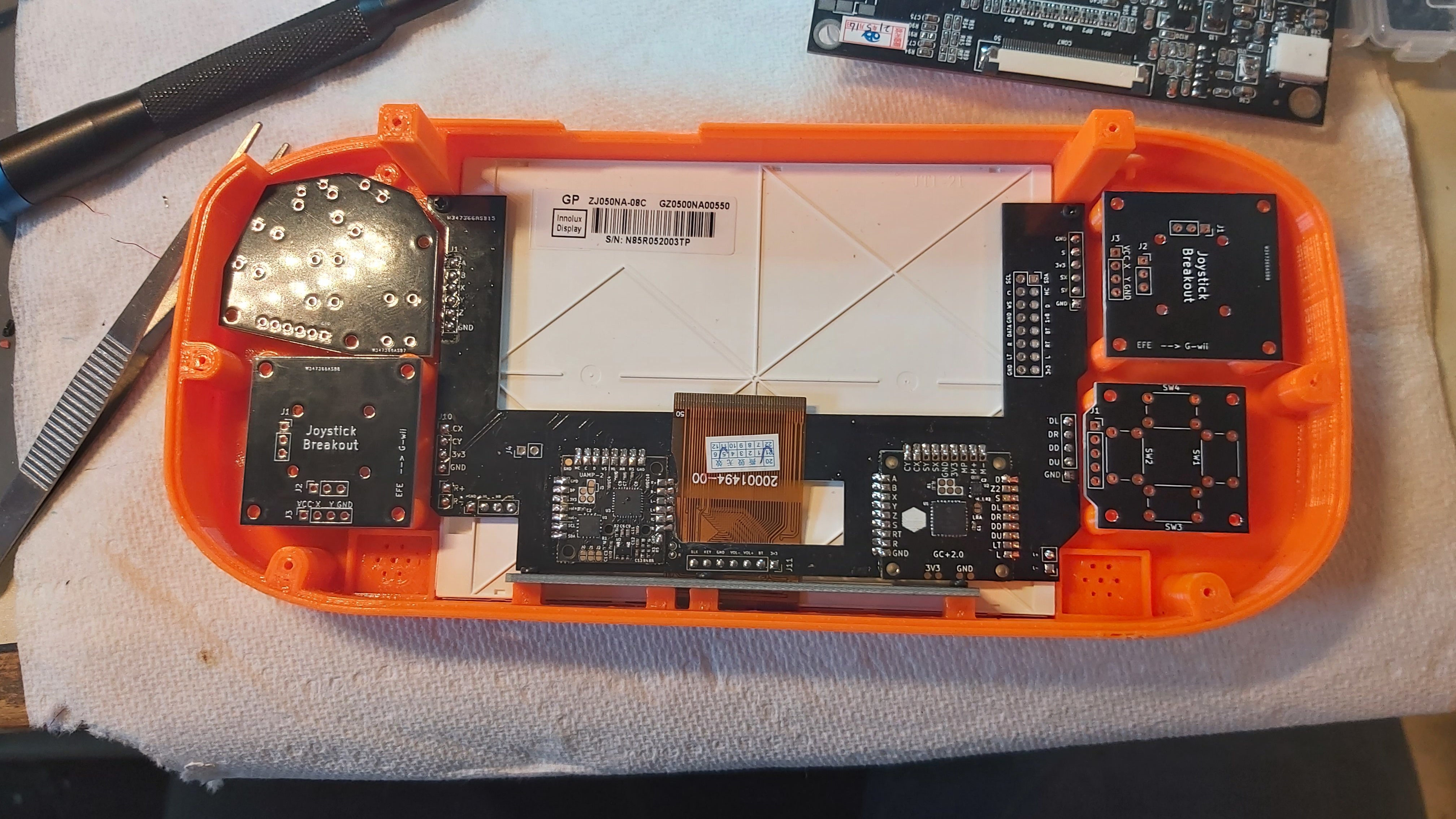
the keen eyed of you may have notice the horrible screen flex placement, apparently I forgot how to count in the cutout location
as a result I had to trim down the PCB as close as possible to the U amp solder pads and even trim the Screen flex to fit, thankfully it was just unused ground space on my board and the screen so i think it may work, hopefully...
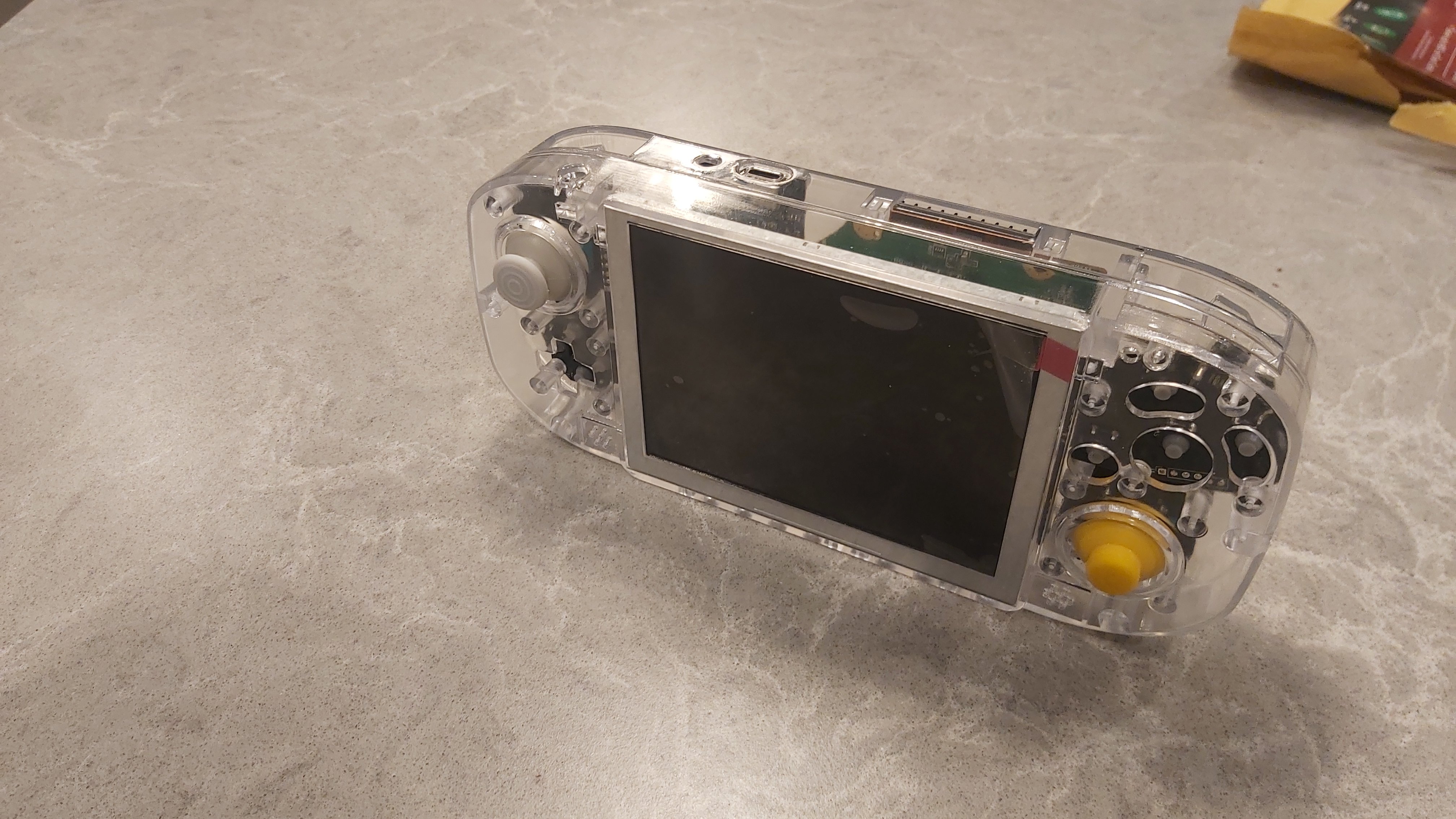
last thing for now i just needed the beauty shots to see what its gonna look like so here's some teasers
4 layer boards looking amazing and its cool that you can see the top side of the mobo
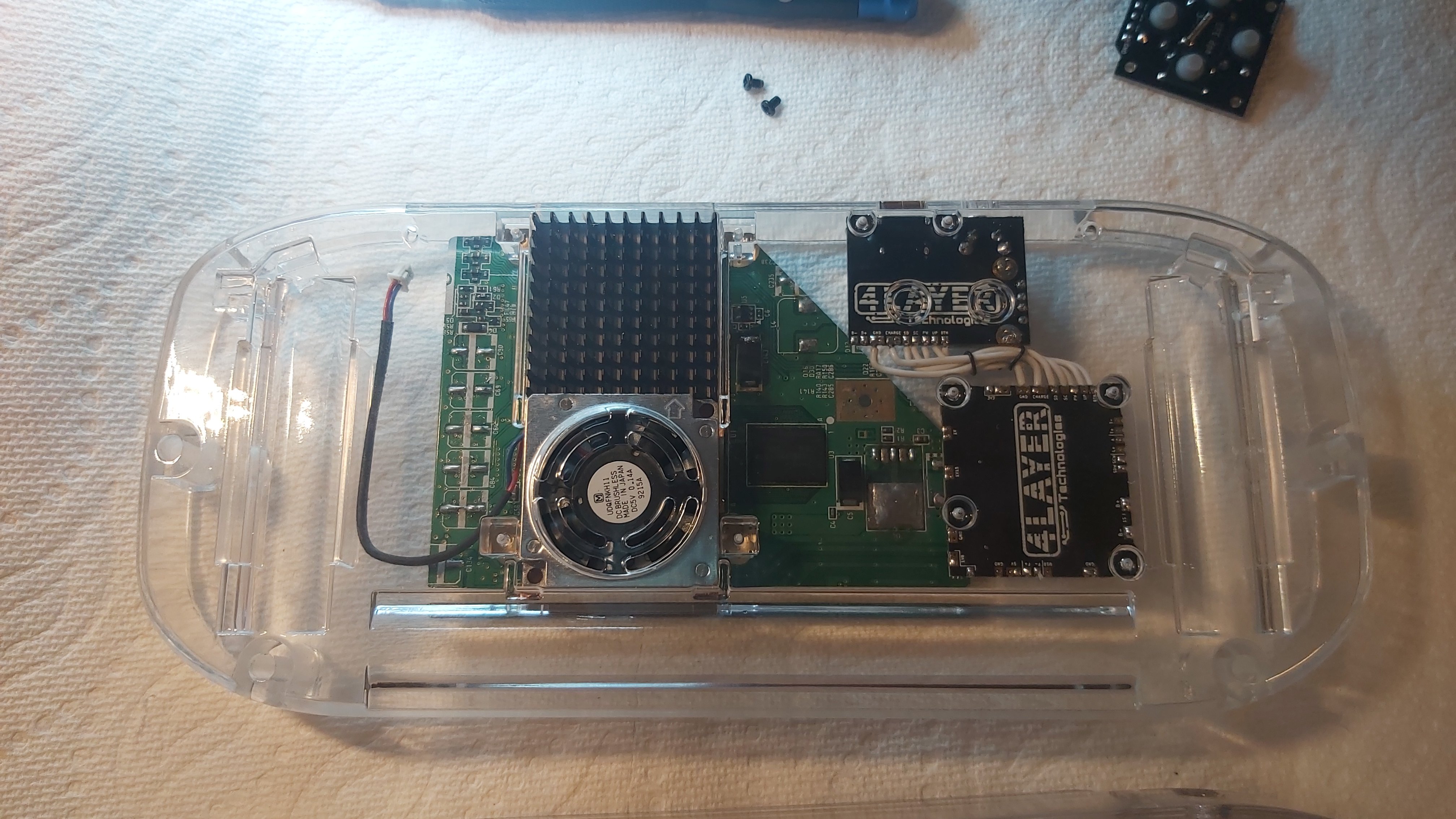
with the black GC PCBs joysticks and screen test fit it looks pretty good
now that ive got the all the needed wire and the rest of the parts i can continue on building in the orange case and ill just be waiting on the M2 tap to get proper threads in the clear shell
oh also clear 18650 sleeves are a thing, soo...
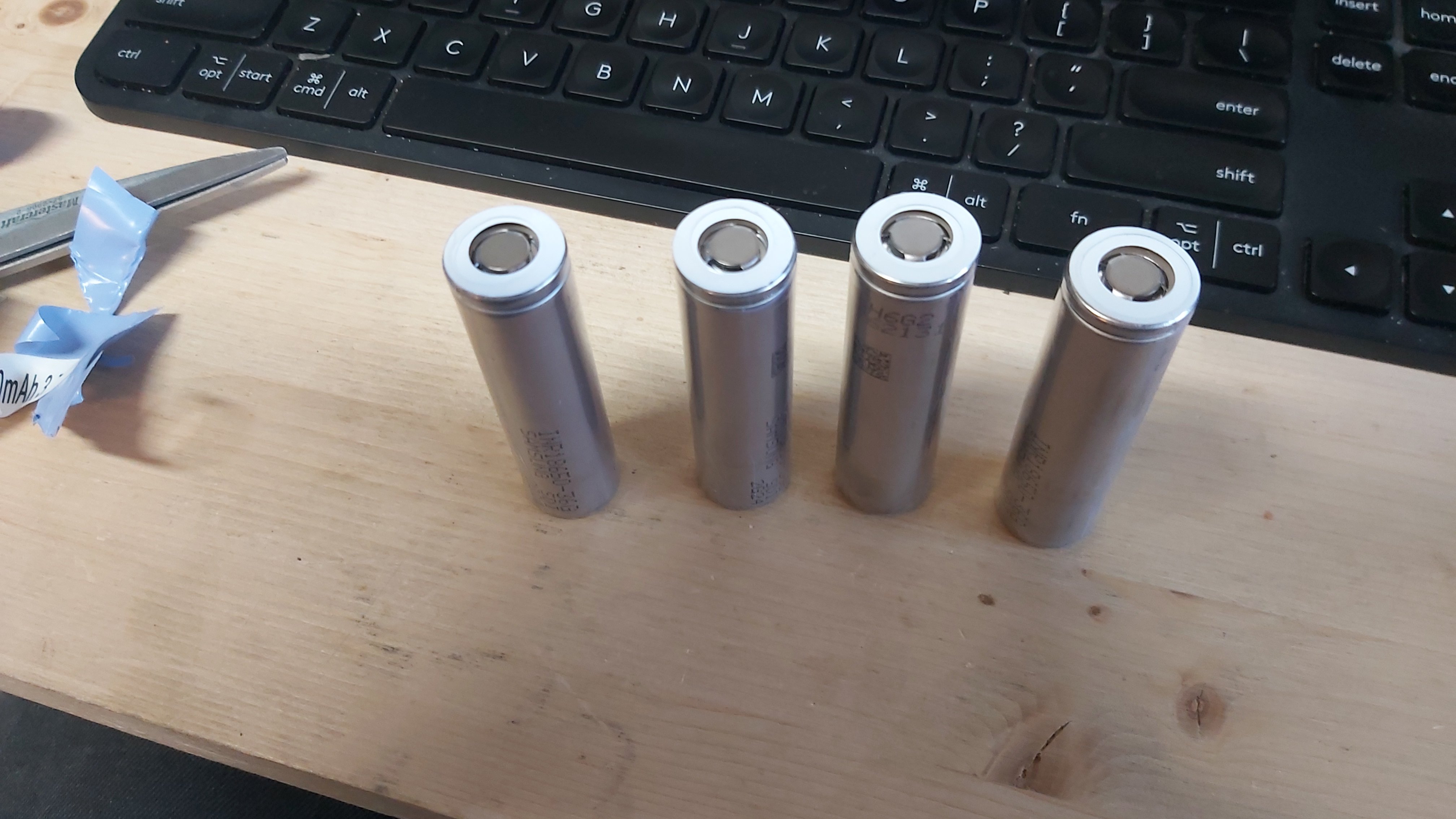
(warning I do not recommend doing this as cutting the sleeves off can short the battery and get it hot and blow up and such)
Thanks to @Gunnar for posting the cool PCB way printing information and @SparkleBear for telling me to get up and make a build log here
(Sorta) day 3 will be coming soon
The Plan
a clear Gwii
Black PCBs
minimal, but all white wiring
lots of patience
I have built a few Gwiis now but wanted one to keep for myself something special
Gman posted the glass gwii for sale and it was gone so fast but looked so good
so a week or 2 later this showed up
this is the same options as Gman used from PCBway
its called UTR-8100 (transparent)
(Sorta) Day 1 of work
it appears to be a bit brittle when a tried a screw carefully so I haven't dared to put any screws very far in yet,
to remedy this I ordered an M2 tap and a corresponding size drill to cut threads for the m2 screws and avoid stripping them all out
SIDE NOTE (high quality wire
)I already had some white 30awg silicone rubber wire, but I had to yet to find some thicker stuff for the power wiring.
I ordered some and it arrived today
i guess 500ft of the (thicker stuff) will do
also
for others to note, i stuck with 24awg since its what i've always used and 22 was about 2x the price
although maybe 500ft was a little excessive
either way I love this wire its super flexible easy to strip and doesn't burn or melt when being soldered to.
(Sorta) DAY 2
to go with the nice clear case I needed to have some nice black PCBs
in my previous build log i showed off my custom GC breakout boards for the gwii and here im building on those. they remain mostly the same though
changes include
1. all PCBS in black now
2.Screen control button board works for black and blue driver boards
3. best for last new PCB to eliminate most of the upper wiring
Screen control board has to sets of resistors to be configured for the BB store blue driver board or the eBay special black one
some of the labels are wrong and I forgot to label the jumper pad which selects the blue driver board or black driver board configuration
Here are some pictures with the GC+ and U amp mounted as I did the first wire up (I have it in a spare orange case to avoid damaging the precious clear shell)
the goal with the big PCB was to reduce the top screen clutter of wires and have almost all of the wiring between haves solder to one spot on the board
I kept the RGB hv lines out cause i don't wanna have any signal losses that could come from being to close to other lines
the Ump i2c lines and GC data line are though so ill have to see if they work well or have any issues
the keen eyed of you may have notice the horrible screen flex placement, apparently I forgot how to count in the cutout location
as a result I had to trim down the PCB as close as possible to the U amp solder pads and even trim the Screen flex to fit, thankfully it was just unused ground space on my board and the screen so i think it may work, hopefully...
last thing for now i just needed the beauty shots to see what its gonna look like so here's some teasers
4 layer boards looking amazing and its cool that you can see the top side of the mobo
with the black GC PCBs joysticks and screen test fit it looks pretty good
now that ive got the all the needed wire and the rest of the parts i can continue on building in the orange case and ill just be waiting on the M2 tap to get proper threads in the clear shell
oh also clear 18650 sleeves are a thing, soo...
(warning I do not recommend doing this as cutting the sleeves off can short the battery and get it hot and blow up and such)
Thanks to @Gunnar for posting the cool PCB way printing information and @SparkleBear for telling me to get up and make a build log here
(Sorta) day 3 will be coming soon
Attachments
-
 618.2 KB Views: 124
 -
 727.3 KB Views: 145
 -
 1,018 KB Views: 148
Last edited: