Worklog Black Beautii -- SparkleBear's G-Wii Rev 2 Worklog. :)

Joined
Jul 9, 2020
Messages
227
Likes
498
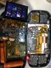
Hey y'all... I finally got started on my Gwii build today. I still don't have all the parts from AliExpress but I couldn't hold back any longer.

I've had so much fun building and dialing in my first portable, a purple Gboy, that I am already excited to make a second portable. Its been so inspiring learning, getting support from the community and offering help in the forums and discord whenever I can! So, the plan is just a standard G-Wii build (thanks Gman), he printed the case for me and is always there to offer support at critical moments! Thanks Gunnar! ... I also want to shout out to @Kraminations for putting together that indepth purchase guide for this build... many thanks dude.

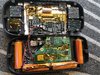
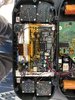
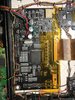
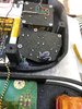
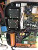
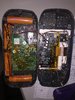
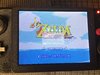
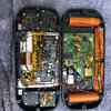
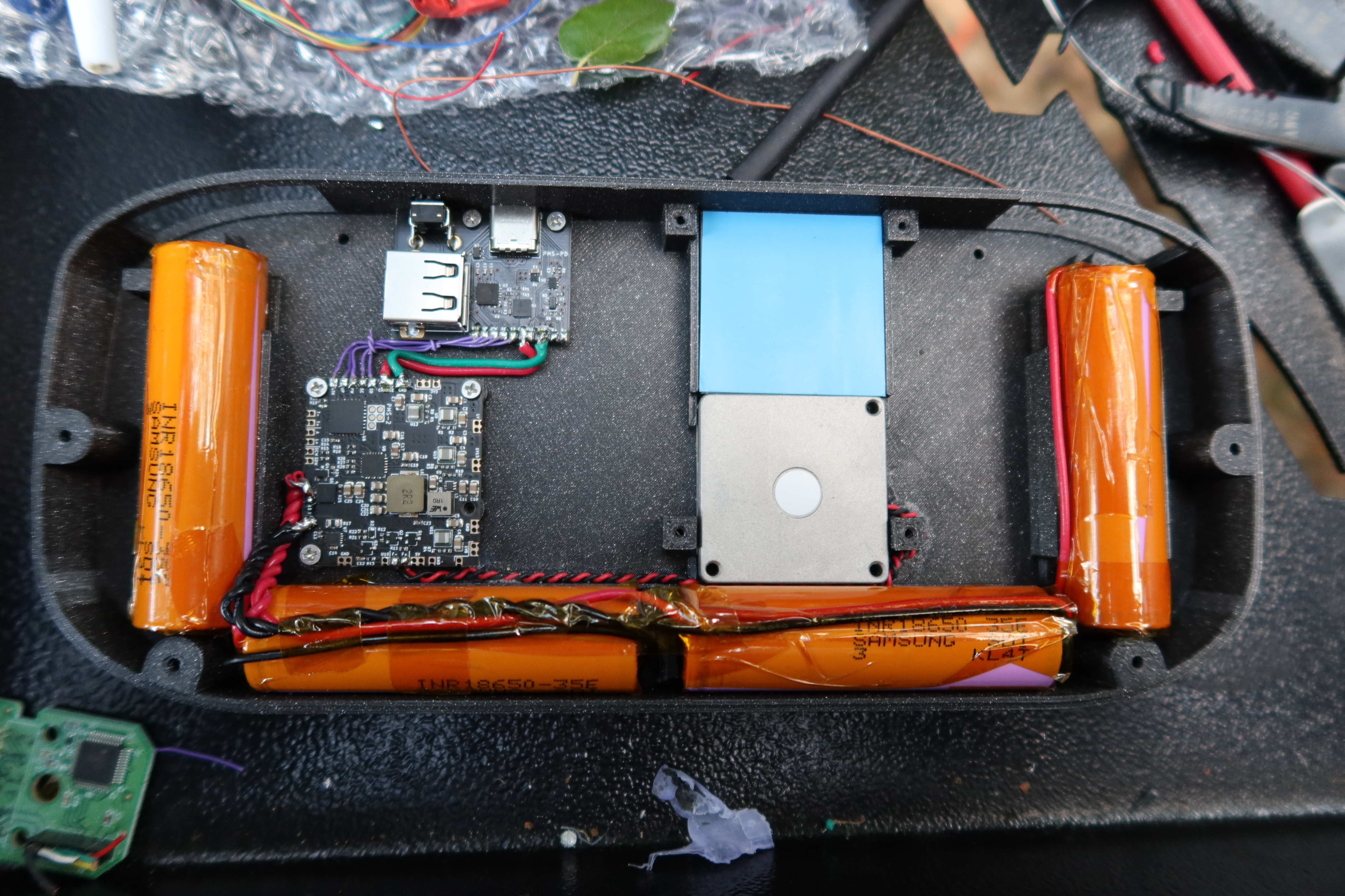
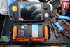
Today I attached the RVL-PMS-2, the USB-PD board, wired up the batteries, wired the fan and attached the stick boxes with caps into the case. I also removed the 110mH inductor from the LCD board and secured the screen into the case. I have been having a really fun time being meticulous with the wiring. I want this build to be as clean and pretty inside as possible... we will see as it progresses but that is the intention.

I plan to do Bluetooth Relocation and MX relocations for sure.

A couple of observations from today's work:

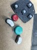
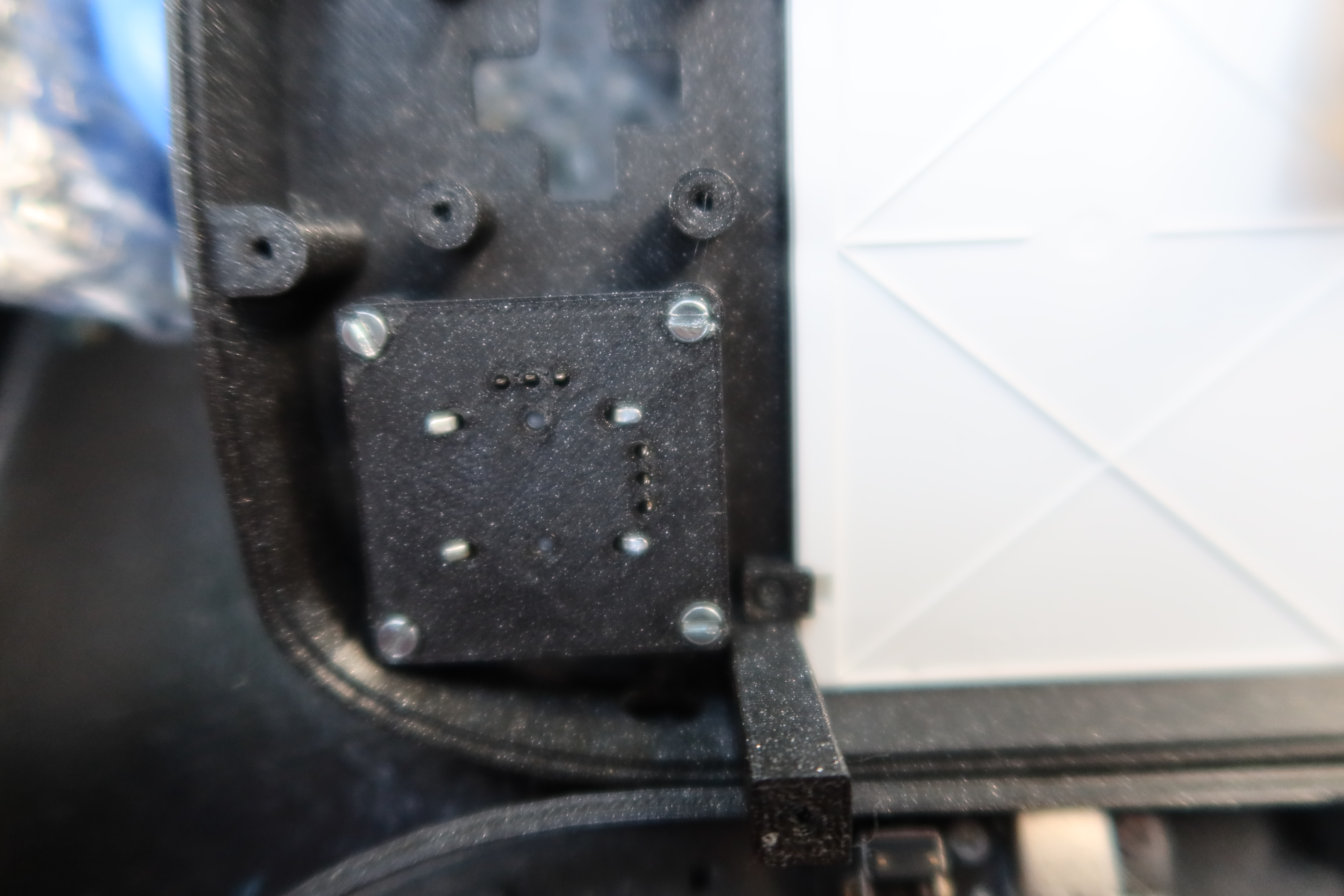
--The after market stick boxes have little nubs that do not exactly line up with the 3d printed back plate, i had to cut one of the nubs off to have it sit flush. The OEM boxes fit perfectly though. I used some super glue on the plastic nubs to make the install more secure. I also bent the legs down so it would be even more secure still.

-- Curious about gauging the wire for the batteries if i chain more than one battery together. I know that ALL positive terminals are electrically connected to eachother and B+ and seperately ALL negative terminals are connected to each other and B-. Im not sure if the photos show but I used 22ga wire to connect the left most pair of batteries in parallel and the right most pair parallel with eachother and then two wires from each pair to the PMS board... So there are two black wires and two red wires ganged and attached to the PMS board. Im curious how the current will flow and if this is good practice or not good practice. Any rumination would be appreciated.

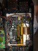
One thing of note with batteries was where the two butt ends meet up... I realized that it would've been safer to put two like charge terminals next to eachother incase the kapton fails and the terminals touch. I did not do that here... but upon this realization i just cut a thick piece of plastic and wedged it between the terminals so that at no point down the road will they be able to touch... If it was two positive or two negatives touching it would not matter because they are already ganged in parallel. Just an observation...

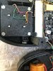
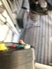
When soldering wires to the ends of the batteries I ended up adding a bit more length to the unit than i wanted. I needed to shave/melt off some of the screwpost so the battery didnt put undue pressure on the bracket below the shoulder button. Not sure if that part will be a problem if its bent a little but but didnt want to chance it... after melting/shaving off some of the post it fit in snuggly with out bending the part.

The PMS is outputting the proper voltages when tested with a meter and the fan runs as expected. The fan seems to make a weird whine sound... not really ideal. Wonder if its just that fan design or if i have a defective unit. I have a second fan I might test... Just something I'm going to keep an ear on as the build goes on.

Questions to ponder:
-How are people attaching the GC+/U-amp board to the g-wii portable. Hot Glue? Did I miss some screw post place?
-Do I want to add HDMI with GCVideo chip from @Skent?
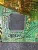
-Is RVK 4 layer board different from the previous late RVL revision 4-layer boards?
-Whats a good carrying case for the g-wii sized portable?
-Add LED resistor so that the indicator light doesn't blind me... or just leave it out and use the monitor in RVLoader to check battery.

Whats next? Well, I'm waiting on the squishy tact switches and buttons... I have a ton of prepped Wii ready for trim... I picked up the samsung SD at best buy today too...

STOKED on this build! Woot! Thanks for all the inspiration out there y'all.
CHEERS!

IMG_0386.JPG
IMG_0391.JPG
 

Attachments

Last edited:
Joined
Jul 9, 2020
Messages
227
Likes
498
Day 2:

Today I tackled the trim and wii wiring. I pulled out a board I thought i had prepped for trimming a few weeks ago but it wouldn't boot! I discovered if I plugged in the Wifi chip it would boot! DOH... but this was a non gamecube board and it would boot right into either priiloader or rvloader. No way to sync wiimote and no way to plug in a GC controller. So first order of business was to cut off a port from a donor wii board and wire it up. I had to move all of the little SMD components over... just so I could navigate menus to reinstall RVLoader with wifi patches... Silly me. All that work just to cut it all off again. Hah, learning experience...
IMG_6901.JPG


After getting the Gamecube controller port attached to the board, NoWifi patch installed, and confirmed to boot without wifi. Ready to trim!

The trim also had some hickups as I ended up sanding the board too small and cut off 6 nand traces... so i spent the next long while learning about those nand lines and wired them by hand from the chip to the vias. 2 hour lesson... I won't likely let that happen again. But it was good practice.

IMG_6903.JPG


After confirming solid connection and no bridges I crossed my fingers and wired up the wii voltages and U10 from the PMS. I also wired up composite video and TIIIIGHTLY wound USB lines. At first the screen would not take the AV signal, i thought i messed up the trim... so I busted out my old gboy 240p screen and confirmed that I successfully fixed the nand and had a successful trim...
IMG_6912.JPG


Then Gman told me that the 5 inch boards only take composite on AV2 not AV1... So after rewiring to the 5inch board on the proper pins, the screen worked. Yay!

IMG_6920.jpg


The fan I purchased and installed here is way too loud and jangly. @Cyframe said the fans he got from the old BB store were super quiet so ill probably snag one of those and replace it down the road. (Link to quiet fan)

Still waiting on tacts, buttoncaps and dpad, copper plate, and some hardware. Going to wait to install cooling and screw down wii before taking on VGA and relocations. Still have not wrapped my mind around how to install the shoulder buttons... one thing at a time :)

Today I am thankful for the help and support from y'all... Especially, @Gman and @Cyframe . Cheers guys. :)

Thanks for checking out the thread, perhaps people can avoid some of the mistakes I encountered today.. CHEERS!
 
Last edited:

cy

.
Joined
Sep 3, 2020
Messages
116
Likes
325
Portables
6
Looks like everything is coming out to be really clean and nice! If you need help with anything else, feel free to let me know. I'm always happy to help when I can!
 
Joined
Jul 9, 2020
Messages
227
Likes
498
Day 3:
Yesterday, I wasn't planning on doing too much so I decided to install the LED because it sounded like a good idea. Little did I know that would turn into a full day of work on the portable... Allow me to explain.

On my gboy, the LED always seemed too bright. I didn't want that to be an issue here so I fashioned a light pipe out of hot glue. I put a piece of kapton tape tightly on the face of the case over the led hole. Hot glue down the chute... LED stuck about 1/2 inch away from opening into the glue. I am pretty happy with the resulting smooth look.


IMG_6937.JPG
IMG_6964.JPG


So, after installing the LED I learned that the addressable LED needs to be switched from standard in RVLoader settings. I didn't have any controls wired up so this brought me to start with the GC+ to wire the sticks (which I do have) so I could navigate but no buttons so I couldn't actually select anything. Now this leads me to doing the Bluetooth relocation... all so I could pair a wiimote and toggle around in the settings........ to test the LED.

The GC+ board went in pretty easily. In this build I want to keep everything as color coded as possible so I can know whats what at a glance... On the GC+: 3.3v signals were going to be orange, Grounds Green, Y axis for sticks are yellow, X axis Purple... Buttons might be blue? Not sure yet.

Bluetooth actually went really smoothly, I learned to scrape the solder mask off of vias (didnt do that on gboy) and it made everything way easier this time around. For the future, I want to get a fiber glass pencil for uncovering the traces that lead to the chip for this relocation... the exact-o just isn't exact enough! After wiring, i fired up the wii and it booted right to the "press a" screen! Success!

IMG_6939.JPG


I tried getting the LED working but couldn't figure it out... it was enough for the day... More tomorrow :)

Thanks to @Gman and @alvaro for the help on this day. :)
 
Joined
Jul 9, 2020
Messages
227
Likes
498
Day 4:

Today, I wanted to sort out the LED situation. After chatting with gman, we tested a standard LED and discovered the power and address lines were not fried. Thought maybe the led might be damaged. But Gman noticed scw and sdw lines were twisted together. So here, I learned that the wires for SCW and SDW (the clock and data that runs between the pms and the wii), cannot be twisted or else things in RVLoader go wacky. This is why RVLoader could not save settings or manage the LED. I ran new straight magnet wires and the LED lit right up after changing the settings. Thanks @Gman ! (ps, gman said that as of this revision of RVLoader the LED green and red are flipped, so theres that)

IMG_6969.jpg


I also wired up the MX chip today... getting the hang of the layout of everything. Made sure the MX was not covering any wires or vias incase i need to re-run/use them in the future for any reason. The 2032 battery tucked into the little cubby behind the wii quite nicely. Double checked pins 11, 12, 13, and 14 were going to the correct vias and fired it up to test... So long gay bowser! Mario 64 boots up.. MX Relocation, CHECK! Thanks to @Nold for ensuring me my slightly smaller mx trim was going to be OK! :)

IMG_6953.JPG
IMG_6956.JPG


I still had some daylight left and decided to work on the screen control board situation. This involved mounting the tact switches to the little 3d printed bracket and relocating the SMD from the daughter board. One side of the 4 screen tact switches are bussed together and tied to ground. The other side of the tact gets its respective SMD resistor soldered to the tip and then the other side of each resistor is bussed together and tied to the single KEY pin on the driver board. All was going smoothly until I dropped the minus key's TINY resistor. I live in the forest so it went into the leaves thinking I would never find it again... I decided i would try to scavange wii trim scraps for resistors that might work in combination. About 20 minutes later I somehow found that original resistor on the ground..... and subsequently destroyed it with too much heat accidentally. Wow... Back to scavenging for another solution. Long story short... it didn't work. Moral of the story, turn soldering iron down when working with SMD components. ;P

Thanks to @Kranimations_YT for taking a photo of the lost resistor on his daughter board so I could confirm the value and order a new one. So that part of the build will be on the shelf til that part comes... Big thanks to @Gman (yet again), @Nold, and @Alvaro too. Couldn't do this with out all your help! :)

Soon I'll have squishy tacts, button caps so I can finish the controls. Next big one is the audio amp and the last thing will be VGA... Exciting.
 
Joined
Jul 9, 2020
Messages
227
Likes
498
Day 5:

Today I didn't have a ton of time to work on the project. Package came with copper plate, squishy tacts, button caps and resistors for the button board. I fixed the button board with out too much issue. Not as low profile as with SMD but these little 1/4watt resistors will do just fine... Populated the D-pad bracket with gray tacts.
1C0EB148-2DAF-4165-8504-9B7E93322A94.jpeg
BC79D59F-4A3B-44B2-B263-6C1E40329DCC.jpeg

Cut the copper plate, squirted some thermal paste on the chips and screwed the mobo down. I powered up the unit and let it sit idling for about 40 minutes; it hovered around 50c... Seems we are good there.

Turns out I don't have the circle print back stop for the A button... So I will have to figure that out next...
CF679E91-FE91-4263-BA9B-713AE2A787EE.jpeg
 
Last edited:
Joined
Jul 9, 2020
Messages
227
Likes
498
Day 6:

Yesterday morning I sorted out the button situation. Had to redo x and y a few times to get them to the proper height... Glued them down on the back plates. Used a dab of super glue on a and b soft tacts to keep buttons from rotating. All seems to be good! Meticulously wired them and they all seemed to register in the button tester! Seeing all the buttons in was a good feeling too! WOO!


Before:
button 2.jpeg
button 1.jpeg

After:

IMG_7029.JPG
IMG_7027.JPG


Getting the buttons the right height did wonders for how the feel turned out... I ended up having to glue and break off those back stops a few times. Next time I would probably do more fit testing before gluing... but this is how it went this time.

I had to modify the d-pad plastic cap a bit, pushing up was stuck registering and the sides presses would make down register too... A bit of sanding helped. Pretty much sanded the bottom of the d-pad (not the center nub though) to be flush with the retaining circle. This fixed the mis-registration of inputs.

Next, i went into a bit of tunnel vision and did the whole audio amp and vga back to back... Goal tape in sight was very inspiring.

For the audio amp, I soldered the headphone jack onto the U-amp board and secured it in place with a touch of hot glue. (Little did I know the hot glue melted the insulation and shorted the button board wiring, so lesson learned to not glue big components over wire runs.) Making sure the headphone output was centered in the case hole, I held it there as the glue cooled and hardened. Wiring up the audio was relatively hitch free... fired it up for a test to be greeted with mario's "NIIIIIINTENDOOOOO" call in the opening of mario kart double dash; always a good sign. Now onto the VGA wiring.
IMG_7002.JPG


The VGA wiring seemed to be going smoothly but there were definitely some considerable hitches that still need ironing out. After wiring it up, I discovered you need to also wire 3v3 to the Mode pin (8 on the sheet, but also TP47). The behavior I am experiencing with the VGA wiring is that it is super washed out/blown out with brightness and colors dont seem vibrant or defined. I first noticed the voltages and resistances were off when measuring on pads of display board and at wii board... I touched up some of the solder points and now they measure 38ohms between each of the RGB lines and ground. Even after touching up the points the VGA signal is washed out and strange... So i need to figure this one out in this troubleshooting phase of the build. Here are some photos of the AVE wiring and a shot of the whole board. If anyone sees anything out of place or wrong please let me know how to improve/fix this issue.

Composite video looks like proper colors and I can have brightness and contrast in the middle setting (50) and it seems to display as you'd except. Colors are right, white balance seems correct... even with the brightness and contrast turned down it looks washed out.

Composite photos:
IMG_7036.JPG
IMG_7035.JPG


VGA photos below:
IMG_7039.JPG
IMG_7043.JPG

IMG_7044.JPG


Here are photos of the full innards as well as a close up of the ave wiring:

IMG_7047.JPG
IMG_7048.JPG

IMG_7031.JPG
IMG_7032.JPG

IMG_7030.JPG

Here is a transcript of the troubleshooting process for RGB if anyone else finds this helpful:

StonedEdge—
"Steps should be:
1) Measure the resistance between the RGB lines and GND on the driver board (75 ohms)
2) Measure the resistance between the RGB lines and GND on the wii (75 ohms)
3) Measure the resistance between RGB lines and GND on the driver board connected to the Wii (37 ohms)
4) Measure the resistance between RGB lines and GND on the Wii connected to the driver board (37 ohms). If you dont get those exact values you've done something wrong/your terminating resistors are broken"

Big thanks to @Wesk and @StonedEdge for help late last night with the vga resistances and voltages. And to so many for the encouragement.

Any assistance in sorting out this display issue would be soooo appreciated. Thanks y'all.
 

Attachments

Last edited:
Joined
Apr 12, 2020
Messages
207
Likes
235
Day 5:

Today I didn't have a ton of time to work on the project. Package came with copper plate, squishy tacts, button caps and resistors for the button board. I fixed the button board with out too much issue. Not as low profile as with SMD but these little 1/4watt resistors will do just fine... Populated the D-pad bracket with gray tacts.
View attachment 18303View attachment 18304
Cut the copper plate, squirted some thermal paste on the chips and screwed the mobo down. I powered up the unit and let it sit idling for about 40 minutes; it hovered around 50c... Seems we are good there.

Turns out I don't have the circle print back stop for the A button... So I will have to figure that out next...
View attachment 18305
I wasn't aware that you needed resistors for the G-Wii build (trying to make one now as well). What purpose do they serve?
 
Joined
Jul 9, 2020
Messages
227
Likes
498
I wasn't aware that you needed resistors for the G-Wii build (trying to make one now as well). What purpose do they serve?
I broke the resistors that I harvested from the screen control daughter board.. they come with the screen.... but you can also just incorporate the daughter board into the build but I wanted to save space.

Usually people would use smd resistors but I couldn’t find any on short notice. Hence the through hole style :)
 
Joined
Jul 9, 2020
Messages
227
Likes
498
Ok, so I found some time today to hook up another screen to the gwii to see if I can sort out the vga issue. The other screen/driver board look great!! It’s a relief that the Wii video circuit is normal and not blown out. So that brings me to the 5inch driver board being the issue. Can anyone see something off with components? Might just be worth replacing the whole thing to save the headache...

I had been having a menu glitch on the driver board since the beginning. Even without anything connected to the screen control board header the menu would pop
Randomly but frequently... this is one reason I left the board unobstructed and easy to extract. So replacing it will hopefully resolve both issues :)


1B0B8638-8C22-49A5-9E3A-F4A075DC42DC.jpeg
 

Attachments

Last edited:
Joined
Jul 9, 2020
Messages
227
Likes
498
Great news everyone! The build's final issues seem to have been resolved today! Yahoo!!!

The two remaining issues was the VGA being blown out and the screen driver board control menu would pop up randomly. While chatting with @Gman and Pickles on discord today I shared a pic of my driver board and they both noticed the power was wired into the WRONG electrolytic capacitor. DOH! As you can see in the photo below, the Red wire carrying 5v from the PMS is attached to the right most electrolytic capacitor when it is supposed to be connected to the middle capacitor. Somehow this allowed the unit to power up and function enough to work but cause issues in certain parts of the board.

INCORRECT WIRING:
IMG_7032.jpg


CORRECT WIRING:
IMG_7075.JPG


This totally solved the VGA issue! WOOOO!!! Marvel at the crisp image and proper color balance!

IMG_7071.JPG


So, while I was in there fixing the driver board power rail issue, I touched up the solder joints on the screen control button board... I am no longer experiencing the random menu popups. I am not sure if it was the improper power implementation or a faulty solder joint that was causing the menu popup bug but I am relieved to have sorted that issue out as well... Since the menu bug was appearing even when the key and ground wires from the button board were disconnected from driver board I can only assume it was the power issue. Im keeping an eye out for this issue but so far after hours of testing it has not popped once. Where before it was popping every few minutes. Either way, I am celebrating! Woot!

Here are some Final shots of the build:

IMG_7070.JPG
IMG_7074.JPG
IMG_7075.JPG
IMG_7073.JPG


The coolest part is I finished this while I was on the road... I have been living out of a VW van and have a dope little Portable Portabilizing Station with me wherever I go. :)
IMG_7076.JPG


I want to thank everyone who helped me on the discord while I was going through this build. @Alvaro, @Cyframe, @Kranimations_YT, @Wesk , @StonedEdge, @CrazyGadget, @Militaryman_20, @GingerOfOz... thanks so much for contributing to my growth as an aspiring portabilizer and modder thorugh this process!! Big extra special epic thanks to @Pickles for helping a lot with the final stage of troubleshooting and @Gman for basically making it all possible, answering so many questions and being a super helpful and humble epic dude. Thanks everyone! I'm so grateful and happy to be building with y'all. So much fun and so inspiring...

There is actually ONE more thing I would like to adjust on this console build... It is the light leak from the LED through the rest of the chassis... The plan is to get some thick black touchup paint and just cover the hot glue and led so that it only shines out of the front hole. :) Then its completely done...

Next is another gwii in indigo, using all the skills and knowledge gained from this build... along side some custom PCBs that will tidy up wiring and make screen control board super clean. And perhaps the ashida as soon as its released. Very excited for the coming horizon...

CHEERS! :)
 

Attachments

Last edited:
Joined
May 4, 2021
Messages
6
Likes
4
Wow really thanks for sharing your works with us, this Worklog is really full of information, going through the process of making a gwii with you, you took many photo it really add a lot of value, have a good Time on the road, and looking forward the indigo gwii or any other project you going for
 
Joined
Jul 9, 2020
Messages
227
Likes
498
Wow really thanks for sharing your works with us, this Worklog is really full of information, going through the process of making a gwii with you, you took many photo it really add a lot of value, have a good Time on the road, and looking forward the indigo gwii or any other project you going for
Thanks mate! I appreciate your kind words... When I was setting out to build this, I wanted an in depth log to help me along the way but couldn't find one. I had so much help on discord and learned so much in the process; I wanted other people to be able to make their builds easier. And also, the process was precious and fun for me... so its nice to crystalize it in a log like this too.

Cheers!
 
Joined
Jul 9, 2020
Messages
227
Likes
498
Today I fixed the light leak that would come out through the button gaps from the LED. Pretty simple fix... at first I just tried to use an acrylic paint pen to paint over the we hot glue but the layer laid too thin and wouldn’t cover properly. After letting that the ink dry a bit, I did a sort of paper machete with shop towel and super glue. Laying it layer by layer using tweezers while the led was on to make sure I was covering all the leaks. Once it dried, I then painted it with the black paint pen. Not beautiful or elegant but effective. :)

The last thing I’ll do is swap out the fan for a quieter model. Then this build is physically done. I hope that there will be a software solution to scale the horizontal video aspect. Then this build will be perfect in my eyes...


62BCBF0D-581C-4B4F-81E7-DD5341B7FD72.jpeg
A8457BB2-1B35-4BF5-B6CC-D804F9FBEE7E.jpeg
28B60EDD-B429-47DD-875E-83E65D518C30.jpeg
F4953087-3CFE-4B10-939A-A17DDCBCBFE0.jpeg

No more light leak ! Woo!
 

Stitches

2 and a Half Dollarydoos
Staff member
.
.
Joined
Feb 5, 2017
Messages
3,847
Likes
3,024
Location
Banana Bender Land, Australia
Portables
6
Today I fixed the light leak that would come out through the button gaps from the LED. Pretty simple fix... at first I just tried to use an acrylic paint pen to paint over the we hot glue but the layer laid too thin and wouldn’t cover properly. After letting that the ink dry a bit, I did a sort of paper machete with shop towel and super glue. Laying it layer by layer using tweezers while the led was on to make sure I was covering all the leaks. Once it dried, I then painted it with the black paint pen. Not beautiful or elegant but effective. :)
DIY as fuck, the best kind!
 
Top