
- Joined
- Feb 17, 2020
- Messages
- 3
- Likes
- 3
Hello BitBuilt!
I have finally decided to start working on my first portable, which will be N64-based. Although I have soldered before, and have basic knowledge of using a multimeter, I've come across what is likely an elementary problem - I can't connect to my display.
For my display, I am using this basic 3.5" monitor from Amazon, I've also attached a picture of my controller board for the display, as I've read there are different revisions of the board out there.
https://www.amazon.com/gp/product/B0045IIZKU/ref=ppx_yo_dt_b_asin_title_o01_s00?ie=UTF8&psc=1
I do know both yellow and white are Video 1 and Video 2, respectively. I took this picture for reference before unsoldering these wires from the board in order to remove the back plate of it, which turns out to be a big mistake due to the position I'm in now....
![IMG_2866[4071].jpg](https://bitbuilt.net/forums/index.php?attachments/img_2866-4071-jpg.10881/)
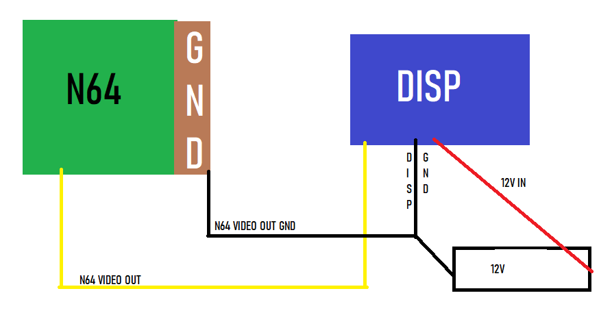
For testing purposes, I stripped a 12V 3.0A power supply and I've tested polarity (verified positive and negative ends) with my multimeter. The basic diagram below shows how everything is currently hooked up, with the yellow wire being soldered to the Video 1 Terminal of the Display Controller.
So in the end, I have these questions to ask:
I have finally decided to start working on my first portable, which will be N64-based. Although I have soldered before, and have basic knowledge of using a multimeter, I've come across what is likely an elementary problem - I can't connect to my display.
For my display, I am using this basic 3.5" monitor from Amazon, I've also attached a picture of my controller board for the display, as I've read there are different revisions of the board out there.
https://www.amazon.com/gp/product/B0045IIZKU/ref=ppx_yo_dt_b_asin_title_o01_s00?ie=UTF8&psc=1
I do know both yellow and white are Video 1 and Video 2, respectively. I took this picture for reference before unsoldering these wires from the board in order to remove the back plate of it, which turns out to be a big mistake due to the position I'm in now....
For testing purposes, I stripped a 12V 3.0A power supply and I've tested polarity (verified positive and negative ends) with my multimeter. The basic diagram below shows how everything is currently hooked up, with the yellow wire being soldered to the Video 1 Terminal of the Display Controller.
So in the end, I have these questions to ask:
- Is everything wired correctly? I'm confident that everything that I am showing above is connected and is fully connected, I just don't know if I have my wires and grounds correct.
- Is my display fried? I don't think so because before I took everything apart, I did connect the display and it did work, but It may have gotten fried in my testing. I've just verified there is voltage going to the panel from the controller by using my multimeter. Is there any way I can force the display on to test?
- Any other tips you can provide to help me along the way?