Question PAL to NTSC Motherboard Help...Please?

Joined
Nov 29, 2017
Messages
61
Likes
56
Location
US
Portables
2
Hi all,

Haven't really been active on here in awhile but recently I've been working on a GameCube related project and ran into an issue, so I thought who would be better to help than the lovely BitBuilt community?

Background: My project is to transplant the BIOS chips (the two MX chips) from a North American GC to my Resident Evil 4 PAL Gamecube. I read on a forum about someone doing this and it made his gamecube act completely as NTSC and he could play all of his NA titles. The great thing about it too is that the GC will still be able to output natively in RGB, since that was a feature only the PAL gamecubes had.

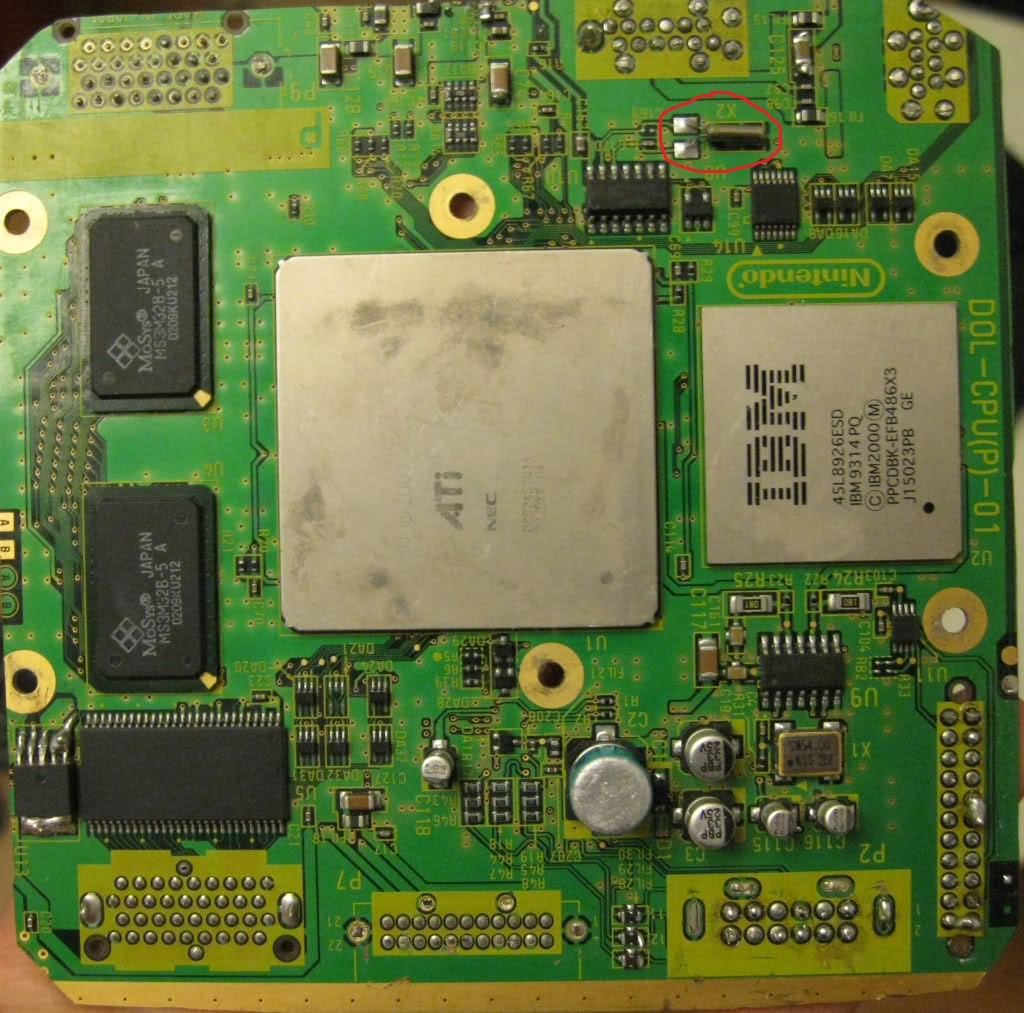
The Question: The same person who did this mod from the forum I mentioned also stated that he replaced harvested the crystal oscillator from the NTSC cube and wired it to the relevant pins on the MX chip after transplanting them. Now he didn't specify what oscillator it was because by the looks of it there are two. Please see below images, silkscreen label for these components are X1 and X2. Also not that each one is close to their respective MX chip and look for the differences between PAL and NTSC.

NTSC Oscillators:

upload_2019-8-13_8-49-52.png

upload_2019-8-13_8-50-18.png


Pal Oscillators:
upload_2019-8-13_8-50-39.png

upload_2019-8-13_8-50-56.png


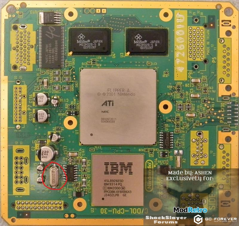
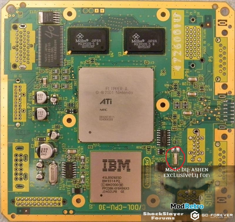
As you can see the only oscillator that looks different between the PAL and NTSC Boards is the one labeled X1. I suppose X2 could still have different frequencies between the two but I'm not sure which is why I wanted to reach out and see if anyone else had more info on this. So to reiterate, Do I only have to swap the X1 Oscillator? Or is it the X2, or both? And if it is only the X1, does anyone know what pins the oscillator is connected to? I broke the casing on mine trying to remove it with a regular soldering iron So I can't really beep it out. Also, if it is the X1 I need to replace, would anyone have a spare oscillator they could ship me if I pay? I don't have a rework station.

Thank you all in advance!
 

Nold

real emulation, no hardware
Staff member
.
.
2021 1st Place Winner
Joined
Jul 16, 2017
Messages
443
Likes
1,608
Location
EU
Portables
5 + 1*π
Hi,

interesting project.. I would just modchip it but whatever..

GC is long time ago, so i might be wrong but i think you're swapping the IPL-Chip?! IIRC that's like the bootrom or sth. so it might hold the region of the cube.. the crystal X2 is the RTC crystal, guess that should be the same on both versions..

hmm.. i just red this on YAGCD:
The RTC MX chip also contains the GameCube's BIOS
So you might wanne swap THE "MX" chip? So it would make sense to also swap the crystal X1, if the clock generation for the chip it's connected to also handles the clocking for CPU/GPU like it did on the N64. But that might also require some changes on the chip, to work on another frequency. or the GC does that on boot?!

I would check where the crystals are connected, too and if there are any datasheets on those.. stuff like that. idk
GC is just sooo long ago for me, i really would love to work with it again, but they got soo expensive >.<''
 
Joined
Nov 29, 2017
Messages
61
Likes
56
Location
US
Portables
2
Hi,

interesting project.. I would just modchip it but whatever..

GC is long time ago, so i might be wrong but i think you're swapping the IPL-Chip?! IIRC that's like the bootrom or sth. so it might hold the region of the cube.. the crystal X2 is the RTC crystal, guess that should be the same on both versions..

hmm.. i just red this on YAGCD:


So you might wanne swap THE "MX" chip? So it would make sense to also swap the crystal X1, if the clock generation for the chip it's connected to also handles the clocking for CPU/GPU like it did on the N64. But that might also require some changes on the chip, to work on another frequency. or the GC does that on boot?!

I would check where the crystals are connected, too and if there are any datasheets on those.. stuff like that. idk
GC is just sooo long ago for me, i really would love to work with it again, but they got soo expensive >.<''
Hey thanks so much for the response! So after looking into the documentation you linked to it appears that the chip near x1 is indeed the clock chip as you inferred, the adjacent crystal is referred to as the clock crystal fitting enough. Found this where someone mentions that you need to replace the x1 crystal when transplanting mx chips but his transplant is from the old 4 pin crystal to the 2 pin where I need to swap the other way around. That being so, I still need some sort of pinout for that oscilattor, are two pins on the same side just connected to eachother? Can't seem to find a datasheet for it. And I'll still also need a new crystal itself haha.
 
Joined
Jul 9, 2019
Messages
22
Likes
37
The device used on those older GC boards is an oscillator module with an integrated xtal, rather than just an xtal. You need to connect all 4 pins up.

1: Enable - this has to be pulled high (to Vdd) to turn the output on
2: GND
3: Output - connect to pin 5 of the MX clock synth chip using a small cap (say 22nF)
4: Vdd - positive supply - take this from the supply to the MX chip

In theory, the supply should have extra filtering on it, but you can generally get away without it.

It's not likely to affect you because you are planning on using RGB, but note that this mod will make the GC output composite signals with a 3.58MHz NTSC color subcarrier. This is obviously fine for 60Hz, but there are a lot of monitors that don't play nice with 50Hz NTSC and hence might give you seriously messed up colors with PAL games.


GC_Oscillator.jpg
 
Joined
Nov 29, 2017
Messages
61
Likes
56
Location
US
Portables
2
The device used on those older GC boards is an oscillator module with an integrated xtal, rather than just an xtal. You need to connect all 4 pins up.

1: Enable - this has to be pulled high (to Vdd) to turn the output on
2: GND
3: Output - connect to pin 5 of the MX clock synth chip using a small cap (say 22nF)
4: Vdd - positive supply - take this from the supply to the MX chip

In theory, the supply should have extra filtering on it, but you can generally get away without it.

It's not likely to affect you because you are planning on using RGB, but note that this mod will make the GC output composite signals with a 3.58MHz NTSC color subcarrier. This is obviously fine for 60Hz, but there are a lot of monitors that don't play nice with 50Hz NTSC and hence might give you seriously messed up colors with PAL games.


View attachment 9272
Thank you so much! This is exactly what I needed.

This might be a stupid question, but I'm assuming pin 5 on the MX chip would be the 5th pin from the left on the bottom row when looking at the chip with the dimple on the bottom left corner, is that correct? And do you know which pin is VDD?

Also, would you happen to have a spare mobo to pull an oscillator from? Or maybe just a scrapped mobo altogether? Or is there any distributors that would sell this standalone osc. module online?

Thanks again!
 
Joined
Jul 9, 2019
Messages
22
Likes
37
Thank you so much! This is exactly what I needed.

This might be a stupid question, but I'm assuming pin 5 on the MX chip would be the 5th pin from the left on the bottom row when looking at the chip with the dimple on the bottom left corner, is that correct? And do you know which pin is VDD?

Also, would you happen to have a spare mobo to pull an oscillator from? Or maybe just a scrapped mobo altogether? Or is there any distributors that would sell this standalone osc. module online?

Thanks again!
Correct - the pin numbering starts from 1 on the pin with the dimple on it, goes up from left to right along the bottom row of pins and then from right to left on the upper set of pins. The power pins are 1 and 14 (I.E. the two pins at the extreme left of the device).

Unfortunately, I had a big clearout a while back, and I don't have any spare boards now - luckily, 54MHz is a standard frequency, so it's easy to get - this one looks like a reasonable option, and has the same pinout as the original.

https://www.mouser.com/ProductDetai...=sGAEpiMZZMt8zWNA7msRCoumSr43LkWRw/jWzA9CeZQ=
 
Joined
Nov 29, 2017
Messages
61
Likes
56
Location
US
Portables
2
Correct - the pin numbering starts from 1 on the pin with the dimple on it, goes up from left to right along the bottom row of pins and then from right to left on the upper set of pins. The power pins are 1 and 14 (I.E. the two pins at the extreme left of the device).

Unfortunately, I had a big clearout a while back, and I don't have any spare boards now - luckily, 54MHz is a standard frequency, so it's easy to get - this one looks like a reasonable option, and has the same pinout as the original.

https://www.mouser.com/ProductDetail/Kyocera-Electronic-Components/KC5032A540000C10E00?qs=sGAEpiMZZMt8zWNA7msRCoumSr43LkWRw/jWzA9CeZQ=
Perfect! Thanks so much again, this should be all I need!

One last quick question if you have an answer, before I looked into the crystal stuff I just tried booting the cube with just having the two MX chips transplanted (no oscillator transplant) and it didn't do anything other than the LED coming on, the disc didn't even spin. Can that be explained due to the oscillator not being the right frequency? Or did I fry my cube by not having the right oscillator for the right chip?

In the meantime I'm going to order that part.
 
Joined
Jul 9, 2019
Messages
22
Likes
37
Perfect! Thanks so much again, this should be all I need!

One last quick question if you have an answer, before I looked into the crystal stuff I just tried booting the cube with just having the two MX chips transplanted (no oscillator transplant) and it didn't do anything other than the LED coming on, the disc didn't even spin. Can that be explained due to the oscillator not being the right frequency? Or did I fry my cube by not having the right oscillator for the right chip?

In the meantime I'm going to order that part.
I don't know for sure how it's set up - but it's certainly entirely possible that the clock synthesizer would disable it's outputs if it's being fed a master clock that's way outside the expected frequency, which would certainly be the case if you attempted to clock the NTSC version with the clock from a PAL unit.

Also note there are two different variants of the U9 chip used in NTSC units - the one that comes from the early NTSC units with a separate GPU clock oscillator won't work at all on a PAL motherboard. You can tell which version it is by looking at the board it came from - if the pads for X3 (to the left of U9 in my photo) are empty or just not there at all you have the right version.
 
Joined
Nov 29, 2017
Messages
61
Likes
56
Location
US
Portables
2
I don't know for sure how it's set up - but it's certainly entirely possible that the clock synthesizer would disable it's outputs if it's being fed a master clock that's way outside the expected frequency, which would certainly be the case if you attempted to clock the NTSC version with the clock from a PAL unit.

Also note there are two different variants of the U9 chip used in NTSC units - the one that comes from the early NTSC units with a separate GPU clock oscillator won't work at all on a PAL motherboard. You can tell which version it is by looking at the board it came from - if the pads for X3 (to the left of U9 in my photo) are empty or just not there at all you have the right version.
So I checked and the X3 module is missing (pads are present) so it think I’m good then?

That also makes me want to ask, I’m assuming I remove the existing x1 from the pal cube altogether? And out of curiosity, it looks like one side of that xtal goes to pin 5 and the other to pin 6. Do we disregard pin 6 altogether when transplanting in the xtal module from the ntsc cube?
 
Joined
Jul 9, 2019
Messages
22
Likes
37
Yeah, if the pads on the board are empty then you have the right version. You should remove the xtal that's currently in the X1 position on the board. I think it has load caps between the xtal pins and ground too - in which case you should remove the one that's on the pin that goes to pin 5 of the chip.

The way the circuit works is that inside the chip there is an inverting amplifier between pins 5 and 6 - so if you connect a crystal between them it will start to oscillate at the resonant frequency of the crystal (since that's where it generates 180 degrees of phase shift to compensate for the inverting amplifier). In the external clock mode, you just feed in the signal to pin 5 and ignore pin 6.
 
Joined
Nov 29, 2017
Messages
61
Likes
56
Location
US
Portables
2
Yeah, if the pads on the board are empty then you have the right version. You should remove the xtal that's currently in the X1 position on the board. I think it has load caps between the xtal pins and ground too - in which case you should remove the one that's on the pin that goes to pin 5 of the chip.

The way the circuit works is that inside the chip there is an inverting amplifier between pins 5 and 6 - so if you connect a crystal between them it will start to oscillate at the resonant frequency of the crystal (since that's where it generates 180 degrees of phase shift to compensate for the inverting amplifier). In the external clock mode, you just feed in the signal to pin 5 and ignore pin 6.
That makes sense. I think I should be good to go then!! I've already ordered that module you linked me to so when it arrives I'll update the thread on my progress. Thanks again for your prompt replies, you gave me all the info I needed!
 
Joined
Nov 29, 2017
Messages
61
Likes
56
Location
US
Portables
2
Great News -- It's working! I removed the stock xtal from the PAL cube and added the module i bought from mouser, wired to the correct pins based on the info Trimesh provided. I skipped the 22nF cap because frankly I forgot to order it and figured it wouldn't be a huge deal wiring it without it right?

At first, the RGB output was very color faded/distorted as you can see below:
upload_2019-8-20_9-26-26.png


But then I tested composite video and it looked just fine:
upload_2019-8-20_9-26-45.png


So my next hypothesis was that I needed a sync stripper for my RGB cable, since I've had color problems with other systems on my display when it's just straight sync on composite. Added the sync stripper and now look at the result:
upload_2019-8-20_9-44-21.png


More importantly, look at the difference between composite and RGB!
upload_2019-8-20_9-45-1.png


One thing I did notice is that everytime I turn on the gamecube now, it asks me to adjust the time settings. Is there something that I messed up?
 

Attachments

cheese

the tallest memer in town
Staff member
.
.
.
Joined
Mar 2, 2016
Messages
2,758
Likes
2,422
Location
Florida
One thing I did notice is that everytime I turn on the gamecube now, it asks me to adjust the time settings. Is there something that I messed up?
The RTC battery is on the controller ports board, if it got shorted or it's just died you'll probably have to replace it
 
Joined
Jul 9, 2019
Messages
22
Likes
37
Great News -- It's working! I removed the stock xtal from the PAL cube and added the module i bought from mouser, wired to the correct pins based on the info Trimesh provided. I skipped the 22nF cap because frankly I forgot to order it and figured it wouldn't be a huge deal wiring it without it right?
If it's working, then don't worry about it - it's just there as a DC block to compensate for any difference between the bias point of the amplifier inside the chip and the center voltage of the oscillator output - but if the system works then they have to be close enough anyway.

One thing I did notice is that everytime I turn on the gamecube now, it asks me to adjust the time settings. Is there something that I messed up?
As Cheese said, the battery is on the controller port board - also check the FPC cable that goes between the controller port board and the main board.

Are you using a PVM? It varies between models, but most of them don't like being driven with composite video on the sync input much.
 
Joined
Nov 29, 2017
Messages
61
Likes
56
Location
US
Portables
2
The RTC battery is on the controller ports board, if it got shorted or it's just died you'll probably have to replace it
If it's working, then don't worry about it - it's just there as a DC block to compensate for any difference between the bias point of the amplifier inside the chip and the center voltage of the oscillator output - but if the system works then they have to be close enough anyway.


As Cheese said, the battery is on the controller port board - also check the FPC cable that goes between the controller port board and the main board.

Are you using a PVM? It varies between models, but most of them don't like being driven with composite video on the sync input much.
Thanks for the info y'all, I'll have to check the battery/shorts and connections as you guys said. @Trimesh: It's actually a plasma flatscreen that accepts RGB. I know, strange right? I didn't even know it took RGB the first 5 months of me having it lol.

Got some worse news though. I was playing Luigi's Mansion last night and had the game paused for a few minutes, when I went to unpause, the cube locked up on me. Was just staying on the pause screen and I couldn't do anything with the controller. Restarted the cube and it wasn't working anymore, seems like the BIOS isn't loading again because it's getting power but the disc isn't spinning. Even worse: I lost my Luigis Mansion progress! Haha

One thought I had is that I never inspected to see what voltage those MX chips are connected to. Has to be either 5 or 3.3 right? If it's 5v, then my guess would be that I fried the oscillator module as it's rated for 3.3v, and it was just able to handle the excess voltage at first for a short amount of time. Before I take it apart again anyone know what voltage line those MX chips are connected to? Or have any other insight on this issue?
 
Joined
Jul 9, 2019
Messages
22
Likes
37
They both run from 3.3V - in fact, from what I remember nothing on the GC main board actually uses 5V - it just goes to the disc drive connector and the controller and AV ports. If you're getting lockups, try putting that cap in - it certainly won't hurt and it might help.

Sounds like you got lucky with the monitor - displays that accept RGB are not that common in the US.
 
Joined
Nov 29, 2017
Messages
61
Likes
56
Location
US
Portables
2
They both run from 3.3V - in fact, from what I remember nothing on the GC main board actually uses 5V - it just goes to the disc drive connector and the controller and AV ports. If you're getting lockups, try putting that cap in - it certainly won't hurt and it might help.

Sounds like you got lucky with the monitor - displays that accept RGB are not that common in the US.
Yeah maybe I'll order the cap and see if it makes a difference. It seems to be like an overheating thing or something based on a time factor, because when I went to turn it on the next morning the cube booted up just fine, played for awhile and then it froze again. Let it cool off, then it came back on just fine. Weird, I'm not sure why the oscillator module would be overheating if it's being supplied the right voltage?

And yeah I got super lucky, I play my current gen and old school games on that same display and they all look great! At least the console that output RGB do haha. It's plasma so it still will get burn-in if you're not careful though
 
Top