What did you do different that made it work?I havent tried connecting to the internet yet but the Wii boots every single time so that's all that really matters right.
You are using an out of date browser. It may not display this or other websites correctly.
You should upgrade or use an alternative browser.
You should upgrade or use an alternative browser.
Worklog Gman's Wii portable
- Thread starter Gman
- Start date
- Joined
- Feb 25, 2016
- Messages
- 1,465
- Likes
- 3,020
Kept my wires short and added more ground/3.3v wiresWhat did you do different that made it work?
![IMG_20160320_174031338_HDR[1].jpg](/forums/data/attachments/0/81-01ccdabc65b401143af3a65ce2b8bf92.jpg?hash=AczavGW0AR)
Damn, quit being such a tease! ")
That looks really nice! Rough estimate on playtime yet or no?
That looks really nice! Rough estimate on playtime yet or no?
- Joined
- Feb 25, 2016
- Messages
- 1,465
- Likes
- 3,020
I'll be doing a lot of extensive testing on this for sure. Should last 2-3 hours probably. Longer than a GCp for sureDamn, quit being such a tease!
That looks really nice! Rough estimate on playtime yet or no?
")
Looks awesome! Can't wait for a video!
All the hard work on the Wii front is making for some epic consoles!
All the hard work on the Wii front is making for some epic consoles!
- Joined
- Feb 25, 2016
- Messages
- 1,465
- Likes
- 3,020
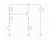
So I want one of the screen buttons to double as the sync button instead of having a dedicated button that probably will never be used. I figure I can use a pnp transistor that shorts 3.3v to the bluetooth module when the screen button is grounded. Although I'm studying electrical engineering, I dont know too much yet. Would something simple like this work?
Attachments
![IMG_20160321_244933663_HDR[1].jpg](/forums/data/attachments/0/83-5abc12aed89aa61b05f42cf04a44275a.jpg?hash=WrwSrtiaph)
EDIT: Sorry, I misunderstood your question previously.
Still your solution won't work (it won't do anything ).
).
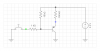
Actually the best way would be using a DPST tact switch, but if you really want to make that kind of circuit, just do it like the circuit that I attached. The green dot is your screen button, while the blue dot is the sync button.
When pressing the button the "blue dot" voltage will drop at around 1V, that should be recognized as a low input
No, it won't work. With that diode the base voltage will always be at 3.3V, replace it with a 1k resistor and use a 10k one as a pull-up.
Also you have to add a resistor load to the collector of your transistor, otherwise after pushing the button and then releasing it the collector voltage will never drop to 0V (ideally, in reality it will take a bit due to leakage currents). Just add a 1k resistor from collector to GND.
Still your solution won't work (it won't do anything
).Actually the best way would be using a DPST tact switch, but if you really want to make that kind of circuit, just do it like the circuit that I attached. The green dot is your screen button, while the blue dot is the sync button.
When pressing the button the "blue dot" voltage will drop at around 1V, that should be recognized as a low input
No, it won't work. With that diode the base voltage will always be at 3.3V, replace it with a 1k resistor and use a 10k one as a pull-up.
Also you have to add a resistor load to the collector of your transistor, otherwise after pushing the button and then releasing it the collector voltage will never drop to 0V (ideally, in reality it will take a bit due to leakage currents). Just add a 1k resistor from collector to GND.
Attachments
Last edited:
- Joined
- Feb 25, 2016
- Messages
- 1,465
- Likes
- 3,020
But the Bluetooth needs a high input to activate the sync. My logic was that R1 was a high pullup and when it is grounded, switches the transistor to short 3.3v to Bluetooth. The screen measures current instead of individual button input so the diode is there to prevent voltage from going into the screen and messing up the buttons. I don't know much about circuit design but the Bluetooth needs a high input so I don't think that will work either.
What do you mean with this?The screen measures current instead of individual button input.
I find it hard to believe that the screen measures the current. Most likely it uses a resistive network to handle multiple switches using just few ADC input.
Can you provide a picture of your screen buttons? Also can you check what is the voltage on the button when you press it down?
Is it like GND->Switch->Resistor or GND->Resistor->Switch?Yeah it uses a different resistor connected to ground on each screen input
- Joined
- Feb 25, 2016
- Messages
- 1,465
- Likes
- 3,020
But you said when the button is pressed the voltage will drop to a low input? I need a low button press to trigger a high output to the bluetooth.Ok in this case you can just follow what I said in my previous post (the first think I said)
Also dont you need a diode so the screen doesnt register a false button press when you have the pull up resistor?
I think he ment using a DPST button, it has two isolated switches that both activate with the single button press.But you said when the button is pressed the voltage will drop to a low input? I need a low button press to trigger a high output to the bluetooth.
Also dont you need a diode so the screen doesnt register a false button press when you have the pull up resistor?
- Joined
- Feb 25, 2016
- Messages
- 1,465
- Likes
- 3,020
Oh yeah that would work but my tact switches I have mounted are the standard SPST. I'd rather accomplish this with a circuit.I think he ment using a DPST button, it has two isolated switches that both activate with the single button press.
Dunno much, but this may work (Aurelio?)Oh yeah that would work but my tact switches I have mounted are the standard SPST. I'd rather accomplish this with a circuit.
No, I meant this:
Use the attached schematics
No, it won't work. With that diode the base voltage will always be at 3.3V, replace it with a 1k resistor and use a 10k one as a pull-up.
Also you have to add a resistor load to the collector of your transistor, otherwise after pushing the button and then releasing it the collector voltage will never drop to 0V (ideally, in reality it will take a bit due to leakage currents). Just add a 1k resistor from collector to GND.
Use the attached schematics