
You are using an out of date browser. It may not display this or other websites correctly.
You should upgrade or use an alternative browser.
You should upgrade or use an alternative browser.
Model [Guide / Release] Noldendo Wii Miicro - v1.1
It's pretty much the same as wiring it with PTHs or the OG PSU, just wire the regulator outputs on the PSU to the corresponding voltage rails on the Wii (no need for hand wiring the regs like with the PTHs).Is there an updated guide for building a Noldendo using PSU-Plus ?
kylekoo
.
- Joined
- Jan 10, 2024
- Messages
- 2
- Likes
- 0
I'm currently midway through doing this project and I'm on quite a tight budget. I've successfully relocated the u10 and the board works still. I'm researching about the regs and wondering about resistors. I've read the guide multiple times but I'm struggling to find some that match. Also wondering do I need capacitors? If I get a PSU plus do I still need resistors and capacitors?
If you are going the PTH08080WAH route, you need to hand-wire the feedback resistors and input / output filter capacitors. If you go with a PSU-Plus, all of that is handled on the board and all you need to is wire the regulator outputs to the Wii.I'm currently midway through doing this project and I'm on quite a tight budget. I've successfully relocated the u10 and the board works still. I'm researching about the regs and wondering about resistors. I've read the guide multiple times but I'm struggling to find some that match. Also wondering do I need capacitors? If I get a PSU plus do I still need resistors and capacitors?
kylekoo
.
- Joined
- Jan 10, 2024
- Messages
- 2
- Likes
- 0
I've found some regulators on eBay but I was wondering do I need to know the wattage? What sort of things do I need to look for apart from voltage and amps. And will I still need the resistors or if I set the regulators output to the correct output do I not need the resistors. (Sorry for all the questions I don't wanna mess this up)
Merry Christmas & Happy Holidays everyone, i got a little present for you: Safe sensor bar relocations!
The guide has been updated with "Relocations -> Sensor Bar". Happy gaming.
The guide has been updated with "Relocations -> Sensor Bar". Happy gaming.
zaka
.
- Joined
- Feb 11, 2025
- Messages
- 1
- Likes
- 0
Hello everyone, I'm very confused about all this
This is my first time trimming a Wii, and I'm having trouble understanding the guides. The trimming guide Included is on a different , so I’m unsure which steps apply to this trim
I’m also confused about how to wire all the other things included like the power switch and sync and reset buttons
also why is magnet wire recommended for some connections? Is it just because it’s smaller, or is there another advantage?
what is u10 chip and how do i do the relocation
if someone could make a list saying witch steps of the Wii trimming guide apply to this trim along with how to properly wire up the other thins like buttons psu's and on/off switch that would be greatly appreciated
it would also be great to know witch steps i can do before the Wii trim in order to test it out/ at what points through the project i can test stuff
bobc1674
.
Hello everyone, I'm very confused about all this
This is my first time trimming a Wii, and I'm having trouble understanding the guides. The trimming guide Included is on a different , so I’m unsure which steps apply to this trim
I’m also confused about how to wire all the other things included like the power switch and sync and reset buttons
also why is magnet wire recommended for some connections? Is it just because it’s smaller, or is there another advantage?
what is u10 chip and how do i do the relocation
if someone could make a list saying witch steps of the Wii trimming guide apply to this trim along with how to properly wire up the other thins like buttons psu's and on/off switch that would be greatly appreciated
it would also be great to know witch steps i can do before the Wii trim in order to test it out/ at what points through the project i can test stuff
Magnet wire is recommended because it is small enough to fit in a wii via, and because it makes the soldering easier.
U10 is a chip that sends the signal to the wii to turn on
Not sure on your other questions as i have never built one.
The Noldendo uses the older 6 layer version of the Wii. There is a trimming guide expansion for it here https://bitbuilt.net/forums/index.p...ive-wii-trimming-guide-6-layer-expansion.860/Hello everyone, I'm very confused about all this
This is my first time trimming a Wii, and I'm having trouble understanding the guides. The trimming guide Included is on a different , so I’m unsure which steps apply to this trim
I’m also confused about how to wire all the other things included like the power switch and sync and reset buttons
also why is magnet wire recommended for some connections? Is it just because it’s smaller, or is there another advantage?
what is u10 chip and how do i do the relocation
if someone could make a list saying witch steps of the Wii trimming guide apply to this trim along with how to properly wire up the other thins like buttons psu's and on/off switch that would be greatly appreciated
it would also be great to know witch steps i can do before the Wii trim in order to test it out/ at what points through the project i can test stuff
The relocations and software principles are the same, the pins and vias are just in different locations compared to a 4 layer Wii
fdraghi
.
- Joined
- Dec 20, 2024
- Messages
- 112
- Likes
- 65
- Portables
- Ashida
what is u10 chip and how do i do the relocation
All that information is available right here. Literally on the first post. All due respect, did you try the bare minimum? like... google, maybe? People here are more than happy to answer questions, help troubleshooting and give you a hand but you gotta show that you're putting on the work yourself. Nobody's gonna hold your hand and guide you step by step, dude...
- Joined
- Jul 26, 2025
- Messages
- 10
- Likes
- 0
It's a very professional layout! I've printed out the case and the assorted internal holders. I'm at the point with mine where I'm testing the untrimmed board. It runs everything fine, with one exception: Donkey Kong Country for wii kills the loader after the title screen and forces a reset of RVloader.
On to the trim!!!
On to the trim!!!
- Joined
- Dec 27, 2025
- Messages
- 2
- Likes
- 0
My Wii is an RVL CPU 30 I don’t know solder u10 to a pad of the cpu can u help me pls (sorry for my sentences I am French )
JamesPi
.
- Joined
- May 8, 2024
- Messages
- 124
- Likes
- 87
- Location
- Central Florida
- Portables
- 1x Ashida- FDM Printed, 1x Design in Progress
Hi! Please see here for details on 6-layer relocations: https://bitbuilt.net/forums/threads/the-definitive-wii-trimming-guide-6-layer-expansion.860/My Wii is an RVL CPU 30 I don’t know solder u10 to a pad of the cpu can u help me pls (sorry for my sentences I am French )
- Joined
- Dec 27, 2025
- Messages
- 2
- Likes
- 0
- Joined
- Feb 24, 2026
- Messages
- 1
- Likes
- 0
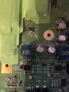
I accidentally destroyed the FIL filter for the IR Sensor bar, does anyone know the value of that so I can order one?