
moahdib
.
- Joined
- Jun 16, 2025
- Messages
- 49
- Likes
- 36
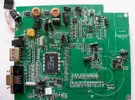
This is my worklog on how I've modded my Lilliput 869GL (8 inch 800x480 TTL LCD) for enabling component (YPbPr) input.
It has the RTD2660 chip which is well known in the modding community. The available inputs on this monitor are the standard HDMI, VGA, 2x AV ports.
My intention is to be able to add YPbPr input for a PS2 portable and get rid of the extra conversion from component to hdmi i was using previously.
My initial attempt was to try and find the firmware source to modify an enable the input but I came across another solution.
Upon some research I came across a post on in a russian forum about LCD's about a service menu on this Lilliput. By holding down the "A/V" button for a few sec. on front of the unit, you are able to access it.

The menu that was most intriguing was the input menu which you can turn on and off every input this chip offers.
This includes:
DVI, PC (VGA), HDMI, YPbPr, SVIDEO, VIDEO1, VIDEO2, TV
Sure enough once you turn on the feature, you can switch inputs normally to the ones that are ON. Some of these inputs are shared such as VIDEO1 and TV.
I went about enabling YPbPr and wiring the inputs to the VGA RGB assuming they would be shared but this did not work.
The RTD2660 has 2 sets of analog RGB inputs on the chip. Only the first input was used whilst the unused 2nd port (pins 31-40) were left not connected.
More to come about this....
The LCD has a proprietary port just below the HDMI port. It is a breakout type cable that gives all the other inputs. With that port removed I mapped all the inputs as shown below. The D+, D- are for USB touchscreen and there is also a mono audio input.


To be continued....
It has the RTD2660 chip which is well known in the modding community. The available inputs on this monitor are the standard HDMI, VGA, 2x AV ports.
My intention is to be able to add YPbPr input for a PS2 portable and get rid of the extra conversion from component to hdmi i was using previously.
My initial attempt was to try and find the firmware source to modify an enable the input but I came across another solution.
Upon some research I came across a post on in a russian forum about LCD's about a service menu on this Lilliput. By holding down the "A/V" button for a few sec. on front of the unit, you are able to access it.
The menu that was most intriguing was the input menu which you can turn on and off every input this chip offers.
This includes:
DVI, PC (VGA), HDMI, YPbPr, SVIDEO, VIDEO1, VIDEO2, TV
Sure enough once you turn on the feature, you can switch inputs normally to the ones that are ON. Some of these inputs are shared such as VIDEO1 and TV.
I went about enabling YPbPr and wiring the inputs to the VGA RGB assuming they would be shared but this did not work.
The RTD2660 has 2 sets of analog RGB inputs on the chip. Only the first input was used whilst the unused 2nd port (pins 31-40) were left not connected.
More to come about this....
The LCD has a proprietary port just below the HDMI port. It is a breakout type cable that gives all the other inputs. With that port removed I mapped all the inputs as shown below. The D+, D- are for USB touchscreen and there is also a mono audio input.
To be continued....
Attachments
Last edited: