Worklog Niimble

Joined
Sep 18, 2025
Messages
9
Likes
12
Hey all,

This will be my worklog for my first Wii project. I've been intrigued by some of the work by others to create small versions of Wii's and GameCubes, so I'd like to have a go at it myself.
In short, my project is heavily based on the Noldendo design (Thanks @Nold for the documentation). However, there are some things I would like to change/add.
In general, I'm a big fan of the idea of all parts being reusable from the original Wii. The things I add are either already owned by me or were very cheap to get.

Here's my current list of requirements:
  • Use a trimmed 6-layer Wii (OMGNOLDii trim)
  • "Custom" heat sink and fan (RPi 5 cooling)
  • Wii2HDMI HDMI out, video quality is good enough for me.
  • PSU Plus (Thanks @CrazyGadget!)
  • USB sensor bar (5V)
  • All four gamecube ports
  • Bluetooth & MX relocated
  • BlueRetro
  • Custom 3D printed case
Lastly, once I've got everything up and running on 12V, I want to bypass the audio amp as well to make everything run at 5V. This way, I can reuse my Raspberry Pi power supply for this project.

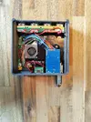
So far, I've relocated and tested U10 before trimming, and after that managed to trim the Wii. Apart from a somewhat rough removal of the GameCube card slots, it went quite smoothly.
Sanded all the edges up to 600 grit, as I didn't have anything finer than that.

WhatsApp Image 2025-09-29 at 21.42.10.webp


Next to that, I did resistance and continuity checks before and after the trim. These were my results:


resistance_values.webp


Comparing before and after trim, it looks like I haven't broken anything so far...
However, I am getting continuity on 1v and ground. Could this be because of its low resistance? Kind of hesitant to hook everything up.
Any advice on this would be greatly appreciated!
 
Yes the continuity beep happens even at low resistence, my Multimeter already beeps at around 40ohms
For a 6 layer the resistences seem fine perfectly normal
 
So, I figured it is time for another update.
After the affirmation of @Viilmo, I hooked everything up to the PSU-Plus, and it booted succesfully!
As I mentioned in my first post, I want to fully integrate the Wii2HDMI for HDMI out.
I removed the AV and sensor bar ports, and directly soldered the Wii2HDMI to the board.
After thorougly checking for any shorts, I booted the Wii and... another successful boot!

Here are some pictures of what it's currently looking like:
WhatsApp Image 2025-10-09 at 09.29.21.webp

WhatsApp Image 2025-10-09 at 09.29.59.webp


While I initially got some succesful boot-ups, after a few days of testing I'm currently just getting black screens.
I'm not quite understanding why this is happening, so I'd like to ask you for help troubleshooting this.

What is happening:
When I'm powering on my Wii, I get a brief blue screen, followed by a black screen. I'm expecting the USB error, but that never shows up.
When I plug in the fan, it is powering on. I've checked all voltages from the PSU-Plus, and they seem to be correct. I'm using the standard Wii power brick for now, so that should be delivering the right voltages and amperages anyway.

What I've tried:
From what I've gathered from other posts on this forum, the U10 relocation might be the culprit. So, I've replaced U10 with the U9 I had kept. This didn't change anything. Then, I resoldered the magnet wire from the one U10 via to another U10 via. This also didn't change anything.
Also, I reflowed all solder joints, especially the joints that looked like cold joints.

At every point during this process, I checked intensively for continuity to ensure nothing was shortened. The fan spinning at least gives me a feeling that I can still revive this board.
Since I got a boot working succesfully before with this exact setup, I don't think the Wii2HDMI is causing this. I remember when installing RVLoader that I did check 'yes' for the VGA option, but I didn't have any problems with this as well before, so I don't see why that should be an issue now.

I've got some cool looking 3D printed parts that I want to show you, but this issue really needs fixing before I can continue with this project.
Does anyone have any ideas what could be the cause, and what I could try to fix this? Any help would be greatly appreciated!
 
You can't use the VGA patch with a HDMI adaptor like that, it only accepts yPbPr. If it worked before, then that was a low power error in the adaptor that was accidentally triggering the yPbPr failover.

You'll need to boot into safe mode and re-run the installer without checking the VGA patch and it should display normally again. You'll have to break and reconnect the mode line while the Wii is powered on to trigger the failover so you can do that
 
Time for another update on my worklog, as I've made quite a bit of progress.
Decided to name this project "Niimble", as I try to create a lightweight, compact Wii.

Thanks to the help from @Stitches, I was able to get the bootscreen to appear again. Nice!

Next to that, I removed the audio amp and connected the inputs and outputs, so the audio now works on 5V and is sufficiently loud for me.
I also succesfully relocated the bluetooth module, which I was quite happy about.

WhatsApp Image 2025-10-19 at 19.37.29 (1).webp
WhatsApp Image 2025-10-19 at 19.37.29.webp


As I mentioned in the first post, I want to use the Raspberry Pi 5 cooling block + fan. For this, I modeled some mounting brackets, and everything fits quite nicely.
This is the 3D printed bracket (printed in PETG) with the cooling block without the lid on top.

WhatsApp Image 2025-10-19 at 18.49.22.webp


And here is the completed cooling system. Just like the Noldendo, the board will be mounted upside down in its case. This means cold air will come in and enter the fan from the bottom, and hot air is blown out to the side. Conveniently, the top lid of the cooling system provides a nice resting spot for the HDMI adapter.

WhatsApp Image 2025-10-19 at 18.50.08.webp


And lastly, I've started the CAD design for the rest of the case. So far, everything fits nicely in my test case.

WhatsApp Image 2025-10-19 at 19.54.01.webp


Next up: adding the USB C board, rocker switch and finishing the case design.
Outer case will also have a cool hinge system to hide/reveal the gamecube ports, so stay tuned!
 
That is crazy small. Basically travel sized.
I tend to sometimes bring my Wii into the office on a Friday afternoon, so yes, having a travel-sized wii that can be powered by USB C reduces a lot of the space and weight bringing it back and forth :D
Total outer dimensions (at least for now) will be 120*116,5*36, making it ~20% smaller than the Noldendo. Although that's an unfair comparison to begin with, as I didn't have to deal with the massive heat sink ;)
 
So, it's been a while, but I'll call this project finished!
First, the beauty shots. I've made a functioning hinge to expose/hide the gamecube ports.

WhatsApp Image 2026-01-11 at 20.25.00.webp
WhatsApp Image 2026-01-11 at 20.25.00 (1).webp


I'm quite happy with the clean look on the backside as well. Just the on/off switch, USB C for power, HDMI out, and two USB ports.

WhatsApp Image 2026-01-11 at 20.25.01.webp


And what's a good project without a final touch of hot glue, right?
WhatsApp Image 2026-01-11 at 20.25.00 (2).webp


During this project, I did see the limitations (mostly temperature-related) with using the 6 layer boards. Therefore, I think I can make a nice V2 of this project using a 4 layer board. But any ways, happy to have successfully finished this project.
 

Attachments

  • WhatsApp Image 2026-01-11 at 20.25.00 (2).webp
    WhatsApp Image 2026-01-11 at 20.25.00 (2).webp
    394.1 KB · Views: 23
Back
Top